

Search keywords:
product name, product type, model number,
test method, manufacturer, technique, application
-
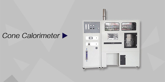
Cone Calorimeter
The import of American VTEC, cone calorimeter ultra high cost performance
more
-
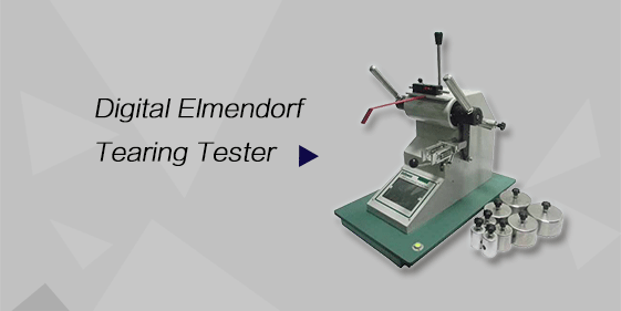
Digital Elmendorf Tearing Tester
Pendulum method test material tear strength, operating more simple, more accurate data
more
-
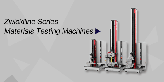
ZwickiLine Materials testing machines
Top of the world's leading universal material testing machine
more
Hydraulic Pump Contamination Resistance Tester
BACK
Standards:
You can operate this tester in compliance with the following standards: ISO 23840:2021 — Hydraulic fluid power — Filters — Evaluation of filter performance using multipass test (MPT) — Particulate filtration efficiency. JB/T 7043-2006 — Hydraulic filter elements — Test method for rupture resistance. GB/T 44682-2024 — Hydraulic fluid power — Filters — Evaluation of dirt-holding capacity of filter elements using multipass test. GB/T 14039-2002 — Hydraulic and lubrication system oil cleanliness evaluation. GJB 1003-1996 — Contamination testing powders and methods for aviation fuel pumps.
Applications:
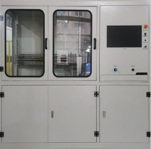
The Hydraulic Pump Contamination Resistance Tester is primarily used to test the fuel pump's resistance to contamination when operating in a working medium with a specified concentration of contaminants.
Product Information:
Hydraulic pump pollution resistance test bench is mainly used to detect the fuel pump in the specified concentration of pollution in the operating medium when the fuel pump to withstand the characteristics of pollution.
Features
1. Highly Targeted Functionality: Specifically designed to evaluate the performance and wear resistance of hydraulic pumps in contaminated fluid environments. It can simulate operating conditions in media with specified contamination concentrations and test the pump's resistance to contamination.
2. Multi-Standard Compliance: Compliant with industry standards such as ISO 23840:2021. JB/T 7043-2006. and GB/T 44682-2024. ensuring compliant and authoritative test results.
3.Practical Structural Design:Equipped with a mixing tank (including agitator), working oil tank, and other components, it supports circulating pump cooling and bypass circulation purification. A manual switching valve allows for switching between two sets of flow measurement devices.
4.Convenient Operation and Monitoring: Integrated control panel and display unit facilitate setting test parameters and real-time monitoring of pump operating status.
Technical Parameters
| No. | Technical Parameters | Specifications |
|---|---|---|
| 1 | Test oil | RP-3 aviation kerosene |
| 2 | Test powder | In accordance with the provisions of Table Ⅱ of GJB1003:1996 |
| 3 | Medium temperature | 10-40°C |
| 4 | Purification cleanliness | /-12/10 (GB/T 14039-2002) |
| 5 | Test flow | 150 ~ 750L/min (fuel pump J/RLB-160; fuel pump J/RLB155-011); 250 ~ 1150L/min (fuel pump J/RLB-162) |
| 6 | Test pressure | 0 ~ 1MPa |
| 7 | Fuel tank volume | 1000L |
| 8 | Equipment power supply | AC 380V / 50Hz |
| 9 | Equipment power | 25KW |
| 10 | External dimensions | 5000 × 200 × 2000 (L × W × H) (subject to measurement) |
| 11 | Weight | 1000kg |
Accessoriess
1. Core Functional Components: Mixing oil tank (including agitator), conical working oil tank, circulating pump, bypass circulation and purification assembly, pump housing fixing device, flow measurement device, manual switching valve.
2. Control and Monitoring Components: Control panel, display screen, oil temperature/pressure sensors, electrical control module.
3. Auxiliary Components: Oil receiving pan, pipe fittings, seals (such as O-rings), instruction manual, certificate of conformity.
Test Procedures
1. Preliminary Preparation
Check the connections and seals of all equipment components (oil tank, circulating pump, pipelines) to ensure there are no leaks; Add hydraulic oil meeting test requirements to the working oil tank, and add contaminant powder according to standards (e.g., GJB1003:1996) to prepare a medium with the specified contaminant concentration.
2. Equipment Start-up and Parameter Setting
Connect the AC 380V/50Hz power supply and turn on the agitator to homogenize the contaminant medium; Start the circulating pump and activate the cooling function to circulate the medium within the system and stabilize its temperature; Set the test parameters (e.g., test pressure, flow rate, running time, etc.) through the control panel.
3. Test Operation
Secure the hydraulic pump to be tested to the pump housing and connect it to the test pipeline; Start the test program, allowing the hydraulic pump to run in the contaminant medium. Monitor the flow rate using a flow measurement device (manually switched by a valve), and simultaneously record the pump's pressure, temperature, and other operating data.
4. Post-Test Processing
After the test, first shut down the hydraulic pump, then stop the circulation pump and agitator;
Remove the test pump and observe its wear, or retest the pump's performance (e.g., flow rate, pressure stability);
Clean the test medium and clean the oil tank, pipelines, and other components.
5. Data Processing and Equipment Cleanup
Process the parameters recorded during the test and analyze the hydraulic pump's anti-contamination performance;
Turn off the equipment power and complete the equipment cleaning and maintenance records.
FAQ
What is this product?
It is a test bench that evaluates the contamination resistance of fuel pumps under controlled polluted fluid conditions.
What is this product used for?
You use it to simulate pump operation in contaminated media, assess performance stability, and verify durability for R&D and quality control purposes.
How does this product work?
It circulates fuel with specified contaminant concentrations through the pump while monitoring operational parameters, measuring resistance to contamination.
Why is this product important?
It ensures fuel pumps meet performance and durability requirements under real-world contaminant exposure, reducing failure risks and supporting design improvements.
Which industries is this product suitable for?
Aviation fuel pump manufacturers, automotive and engine fuel system R&D labs, fuel pump production quality control, and aviation research institutions.
