

Search keywords:
product name, product type, model number,
test method, manufacturer, technique, application
-
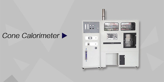
Cone Calorimeter
The import of American VTEC, cone calorimeter ultra high cost performance
more
-
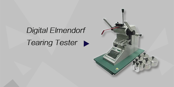
Digital Elmendorf Tearing Tester
Pendulum method test material tear strength, operating more simple, more accurate data
more
-
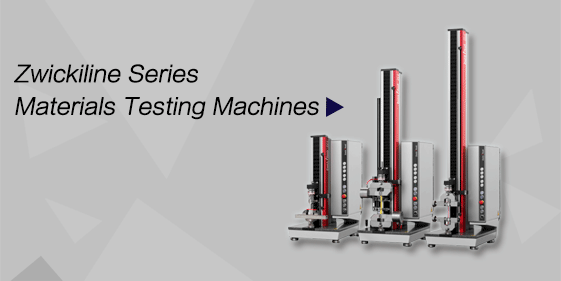
ZwickiLine Materials testing machines
Top of the world's leading universal material testing machine
more
Building Component Fire Resistance Test Furnace – Horizontal Furnace
BACK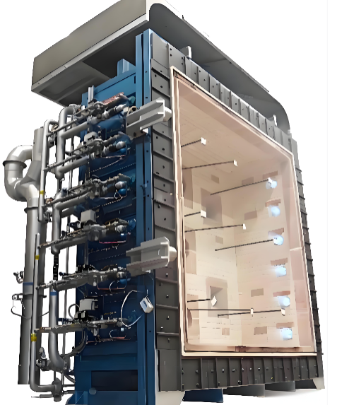

Standards:
Applications:
Product Information:
Structural Description
The furnace shell is fabricated from thickened carbon steel plates with high mechanical strength, welded into structure. The exterior is reinforced with square steel to prevent deformation. The inner and outer surfaces are polished to remove rust, then coated with primer, anti-corrosion paint, and high-temperature paint for surface protection.
Inside the furnace, a thick layer of zirconia-containing high-temperature insulation blanket is first laid to prevent smoke leakage. Then, using 310S high-temperature screws (with superior heat resistance compared to 304 and 201 materials), zirconia fiber modules are embedded and fixed onto the inner wall. This ensures that when the internal temperature reaches 1300°C, the outer surface temperature of the furnace remains close to ambient temperature.
For horizontal testing, lifting of I-beams is required. Therefore, the furnace roof is designed as two movable lifting covers, also installed with high-temperature fiber modules, offering lightweight structure and excellent thermal insulation. The loading beam adopts H-shaped steel with additional welded reinforcing ribs to ensure sufficient load-bearing capacity. For ease of specimen handling, the beam is designed as a rail-mounted structure, allowing it to move aside during specimen installation.
To facilitate operator access, walkways are designed around the furnace body.
To prevent high-temperature exhaust from damaging downstream equipment and electrical components, the system is designed with an exhaust duct at the top of the furnace. The hot gases from the furnace opening mix with cooler air from the top exhaust before being discharged. This
design not only ensures effective smoke evacuation during testing but also reduces the temperature of exhaust gases, significantly minimizing damage to downstream equipment.
To prevent ignition when the exhaust fan is not running (which could damage downstream equipment), a detection device for exhaust fan operation is installed.
To prevent gas leakage or ignition failure when the combustion air fan is not running, a detection device for the air supply fan operation is installed.
The control program allows gas supply only when both the exhaust fan and the air supply fan are confirmed to be operating.
Gas pressure is monitored by a transmitter that sends data to the central processor. If any abnormality is detected, the system will trigger an alarm and prohibit startup.
Standards
The Building Component Fire Resistance Test Furnace – Horizontal Furnace complies with the following standards:
Chinese National / Industry Standards (GB / GA / XF / TB)
GB/T 9978.3-2008 Fire resistance test methods for building components
GB/T 9978.5-2008 Fire resistance test methods for building components
GB/T 9978.6-2008 Fire resistance test methods for building components
GA/T 714-2007 Rapid heating fire resistance test method for fire protective materials for building components.Applicable to fire protection materials for concrete structures, reinforced concrete structures, and steel structures. Fire protection materials for other structural types may also refer to this standard.
GB/T 14907-2018 Fireproof coatings for steel structures
GB/T 28375-2012 Fireproof coatings for concrete structures
GB/T 37267-2018 General technical requirements for seismic bracing systems in buildings
GB/T 29415-2013 Fire-resistant cable trunking systems
(Requires integration with overcurrent detection device and interlocking system)
XF/T 537-2005 Test method for flame retardancy, fire resistance and fire resistance performance of busbar trunking systems
(Requires integration with overcurrent detection device and interlocking system)
GB 51251-2017 Technical standard for smoke control and exhaust systems in buildings
(Refers to GB 17428 test method)
GB 17428 Fire resistance test method for building piping systems
(Strict compliance required. Furnace internal dimensions: 4 m length × 3 m width × 2 m height. For testing a single pipe, one side of the furnace must be designed as an openable/removable structure.)
GB 28376-2012 Fire protection boards for tunnels
GB/T 37613-2019 Steel sections for embedded channels
TB/T 3329-2013 Embedded channels for electrified railway catenary systems in tunnels (China Railway Industry Standard)
Product Functional Features
Furnace Temperature Control
A high-precision data acquisition module is adopted to collect multi-dimensional data such as temperature, pressure, and displacement from multiple channels. The data is analyzed, processed, and controlled by a microcomputer to generate real-time reproduction of actual combustion conditions. The system directly outputs results through computer analysis and judgment. The entire unit uses high-quality components to ensure high performance, high speed operation, and advanced functionality. It supports fully automatic control with excellent stability, repeatability, and reproducibility.
High degree of automation: automatically records test duration and performs automatic timing; allows selection between manual control or automatic tracking of the target curve; automatic furnace pressure control.
One furnace for multiple applications: compatible with various standards and multiple test curves.
Furnace construction: lined with zirconia-containing insulation cotton; when the combustion chamber reaches 1300°C, the outer surface remains at room temperature.
Equipped with automatic fault exclusion for temperature sensors (prevents incorrect average temperature caused by sensor failure, avoiding waste of samples, fuel, and time).
Manual sensor exclusion function allows users to select which sensors to use based on on-site conditions.
Automatic exclusion of faulty furnace pressure sensors (prevents incorrect average values caused by sensor failure).
All sensors can be configured into 5 temperature zones, with freely adjustable sensor quantity in each zone.
The control program includes built-in loading and displacement functions; with additional hardware, horizontal furnace testing can be enabled.
When performing horizontal furnace tests, the number of hydraulic cylinders can be selected, and the loading force is automatically calculated based on the number of cylinders.
Automatic cooling function of the combustion chamber after test completion.
Equipped with anti-misoperation and power failure protection function: after pressing the power button, the system will not shut down until the furnace temperature drops to a safe range; cooling continues first before power is cut off (to prevent high internal furnace temperature from damaging heating elements due to sudden shutdown).
Dual control mode: touchscreen and computer control; can also operate independently via touchscreen without a computer.
Test duration can be set.
Target pressure difference can be set.
Loading force can be set.
Upper computer software developed using dedicated C# software; no installation required—can be used directly by running on a computer.
Burner equipped with flame-out automatic alarm system.
Technical Specifications
|
Item |
Specification |
|
Combustion chamber size (large) |
Width × Depth × Height: (4000 × 4000 × 1500) mm |
|
Combustion chamber size (small) |
Width × Depth × Height: (1500 × 1500 × 1500) mm |
|
Power supply |
Control: AC 220V ±10% / 50–60 Hz |
|
Power rating |
<50 kW |
|
Number of thermocouples |
Total 40 thermocouples |
|
Thermocouple measurement range |
0–1300°C |
|
Number of pressure sensors |
1 |
|
Pressure measurement range |
0–500 Pa |
|
Pressure measurement accuracy |
≤ ±2 Pa |
|
Number of burners |
8 sets |
|
Number of hydraulic cylinders |
4 sets |
|
Hydraulic capacity |
12 × 4 tons |
|
Displacement sensor range |
0–300 mm |
|
Combustion gas |
Natural gas, liquefied petroleum gas (LPG), or propane |
|
Combustion duration |
0–360 min |
|
Number of cylinders |
8 sets |
|
Weight (approx.) |
≈ 5.5 kg |
System Operating Procedure Description
Before Startup:
Install the conditioned test specimen.
If pressure needs to be applied to the specimen, load it 15 minutes before the test. After stabilization, the measured deformation value shall be taken as the zero reference point for this test.
Natural gas: open the manual isolation shut-off valve and check whether the pressure gauge reading is normal.LPG: after opening the explosion-proof room switching valve and manual ball valve, check whether the outlet pressure of the first-stage and second-stage pressure regulators is normal.
Startup conditions: self-check of gas high/low pressure and differential pressure, combustion air blower self-check, and exhaust fan self-check. The system cannot start if any abnormality is detected.
Startup Stage: The gas butterfly valve and exhaust butterfly valve move simultaneously to the preset positions before testing → the main gas valve is activated → the control system initiates the ignition device → high-voltage discharge is generated by the igniter → ignition is performed. After successful ignition, the furnace temperature and internal pressure are automatically regulated.
Safety Interlocks: In case of flame-out during operation, fan failure, gas pressure fault, or blower pressure fault, the system will trigger an alarm and prompt the operator to decide whether to terminate the test or re-ignite.
Safety Protection: After the test is completed, the system performs a purge operation to remove residual combustible gases in the furnace to prevent explosion risk, followed by cooling. The system can only be shut down when the temperature drops below 50°C.
