

Search keywords:
product name, product type, model number,
test method, manufacturer, technique, application
-
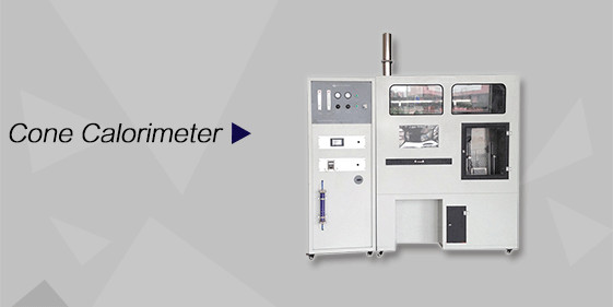
Cone Calorimeter
The import of American VTEC, cone calorimeter ultra high cost performance
more
-
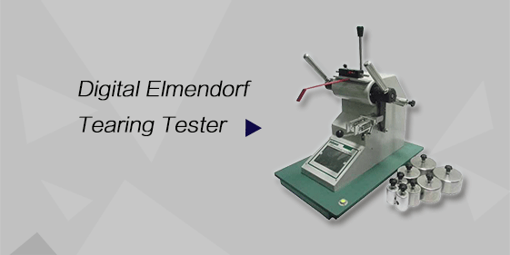
Digital Elmendorf Tearing Tester
Pendulum method test material tear strength, operating more simple, more accurate data
more
-
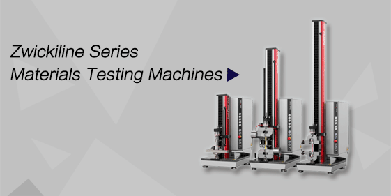
ZwickiLine Materials testing machines
Top of the world's leading universal material testing machine
more
Building Components Vertical Fire Resistance Test Furnace
BACK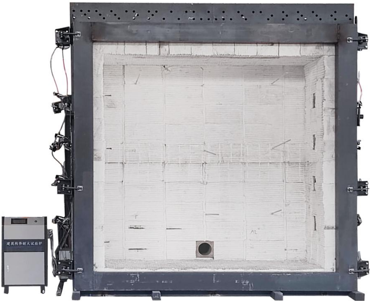

Standards:
Applications:
Product Information:
Standards
The Vertical Fire Resistance Test Furnace for Building Components complies with the following standards:
GB/T 9978.1—2008 Fire-resistance tests—Elements of building construction—Part 1: General requirements (ISO 834-1:1999), which specifies test methods for determining the fire resistance performance of various structural components under standard fire exposure conditions;
GB/T 7633-2008 Fire resistance test methods for doors and shutters (ISO 3008:2007), which specifies fire resistance test methods for door and shutter assemblies installed in openings of vertical separating elements;
GB/T 38252—2019 Fire resistance integrity test method for building doors and windows, applicable to building doors and windows with fire integrity requirements, but not applicable to fire-rated doors and windows;
GB/T 12955-2008 Fire resistant doors, applicable to swing-type wooden, steel, steel-wood composite, and other material fire doors; other opening types may also refer to this standard;
GB 16809—2008 Fire windows, applicable to steel, wooden, and steel-wood composite fire windows with lighting function in buildings; other types of fire windows may also refer to this standard;
GB/T 12513-2006 Fire resistance test methods for glazed elements (ISO 3009:2003), applicable to fire resistance testing of various glazed components such as curtain walls, glass partitions, and other vertically, inclined, or horizontally installed glazed structures;
GB/T 8478-2020 Aluminium alloy doors and windows, applicable to manually operated exterior windows, interior partition windows, pedestrian doors, and vertical roof windows in buildings;
GB 15763.1-2009 Safety glazing materials for building—Part 1: Fire-resistant glass, which specifies technical requirements for fire resistance testing; this standard is used to evaluate the ability of building components to prevent flame and hot gas penetration or post-fire flaming when exposed to fire on one side under standard fire test conditions;
GA/T 714-2007 Rapid heating fire resistance test method for fire protection materials for structural components, applicable to fire protection materials used for concrete structures, reinforced concrete structures, and steel structures; other structural fire protection materials may also refer to this standard;
GB/T 15930-1995 Test methods for fire dampers, applicable to fire dampers used in ventilation and air conditioning systems in industrial, civil, and underground buildings, as well as smoke exhaust fire dampers and smoke exhaust valves;
GB/T 26784-2011 Fire resistance test for building components—Optional and additional procedures (EN 1363-2:1999), applicable to building components or accessories requiring fire resistance testing under specific heating curves and/or additional test conditions during fire exposure. Unless otherwise specified, the standard temperature-time curve defined in GB/T 9978.1 shall be used for fire resistance testing.
Features
A high-precision data acquisition module is adopted to collect multi-channel data such as temperature and pressure. Through computer analysis, processing, and control, real-time combustion information is generated and reproduced. The system performs intelligent analysis and judgment to directly obtain test results. The whole unit adopts high-quality components to ensure high performance, high quality, and high-speed operation, featuring advanced technology. It supports fully automatic control with excellent stability, repeatability, and reproducibility.
High degree of automation: automatic recording of test time, automatic timing, selectable manual or automatic tracking of target curves, and automatic furnace pressure control.
One furnace for multiple purposes: compatible with various standards and multiple temperature-rise curves.
Furnace construction: lined with zirconia-containing insulation cotton. When the combustion chamber reaches 1300°C, the outer surface remains at room temperature.
Equipped with automatic sensor fault elimination for temperature sensors (avoiding errors in average temperature calculation caused by sensor failure, preventing waste of specimens, gas, and time; typically only manual exclusion is available).
Equipped with manual sensor exclusion function, allowing users to select active sensors according to test conditions.
Equipped with automatic exclusion of furnace pressure sensor faults (preventing errors in average values caused by sensor damage).
All sensors can be configured into 5 temperature zones, and the number of sensors in each zone can be freely set (solving imbalance issues in sensor distribution; conventional systems usually use fixed configurations).
The control software includes built-in loading and displacement functions; with additional hardware, it can be upgraded for horizontal furnace testing.
When performing horizontal furnace tests, the number of hydraulic cylinders can be selected, and the loading force is automatically calculated based on the number of cylinders.
After test completion, the combustion chamber features an automatic cooling function.
Equipped with misoperation and power-loss protection: after pressing the power button, the system continues cooling until the furnace temperature drops to a safe range before power is cut off, preventing damage caused by residual high temperature affecting heating elements.
Dual-control system with both touchscreen and computer control; the system can also operate independently via touchscreen without a computer.
Test duration can be set.
Target pressure differential can be set.
Loading force can be set.
Upper-level software is developed using dedicated C# programming; it is portable and can be run directly on a computer without installation.
Burner: equipped with flame-out automatic alarm device.
Parameters
|
Item |
Specification |
|
Equipment Dimensions |
W × D × H: (5500 × 4300 × 4100) mm |
|
Combustion Chamber Dimensions |
W × D × H: (3000 × 1500 × 3000) mm |
|
Power Supply |
Control: AC 220V ±10% / 50–60 HzPower: AC 380V ±10% / 50–60 Hz |
|
Power |
< 50 kW |
|
Thermocouples Quantity |
9 pcs in furnace; 14 pcs for back-wall temperature |
|
Thermocouple Measurement Range |
0–1300°C |
|
Pressure Sensors Quantity |
3 pcs |
|
Pressure Measurement Range |
0–100 Pa |
|
Pressure Accuracy |
≤ ±2 Pa |
|
Burners Quantity |
8 sets |
|
Fuel Gas |
Natural gas, liquefied petroleum gas (LPG), or propane |
|
Combustion Time |
0–360min |
|
Number of cylinders |
8 sets |
|
Weight (approx.) |
≈4 tons |
System Operation Process Description
Before Startup:
Install the conditioned test specimen in place.
Natural gas system: Open the manual isolation shut-off valve and check whether the pressure gauge reading is normal.
LPG system: After opening the explosion-proof chamber switching valve and the manual ball valve, check whether the downstream pressure of the first-stage pressure regulator and second-stage pressure regulator is normal.
Startup conditions: The system will perform self-checks on gas high/low pressure, pressure division, combustion-supporting fan, and exhaust fan. If any abnormality is detected, the system will not start.
Startup sequence: The gas butterfly valve and exhaust butterfly valve simultaneously move to the preset test positions → the main gas valve is activated → the control system triggers the igniter → the igniter performs high-voltage discharge → ignition is carried out. After successful ignition, the furnace temperature and internal pressure are automatically regulated.
Safety interlock: In case of flame-out during operation, fan failure, gas pressure abnormality, or fan pressure fault, the system will trigger an alarm and prompt the operator to determine whether to terminate the test or restart ignition.
Safety protection: After the test is completed, the system performs a purge cycle to remove any residual combustible gas inside the furnace to prevent explosion risk, and then cools down the furnace. The system can only be shut down once the temperature drops below 50°C.
