

Search keywords:
product name, product type, model number,
test method, manufacturer, technique, application
-
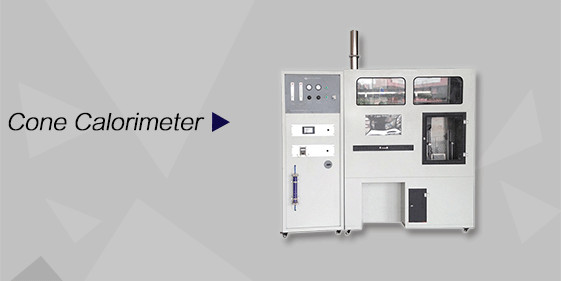
Cone Calorimeter
The import of American VTEC, cone calorimeter ultra high cost performance
more
-
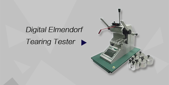
Digital Elmendorf Tearing Tester
Pendulum method test material tear strength, operating more simple, more accurate data
more
-
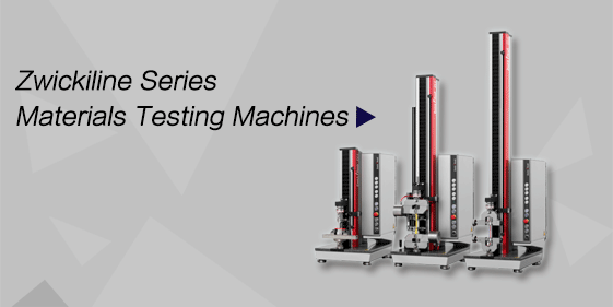
ZwickiLine Materials testing machines
Top of the world's leading universal material testing machine
more
Single Burning Item Test Apparatus for Building Materials
BACK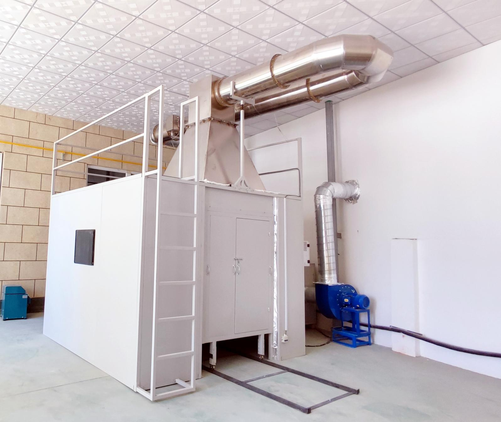

Standards:
Applications:
Product Information:
This test apparatus is a specialized testing instrument used to evaluate the reaction to fire of building materials or products (excluding flooring materials) under single burning item conditions, in order to determine their intrinsic physical performance. The apparatus complies with the testing conditions specified in national standards and follows the prescribed test procedures (methods).After testing with this apparatus, the combustion performance (classification) of the sample can be determined, including quantitative (qualitative) parameters such as: heat release rate of the sample, whether lateral flame spread occurs, calculation of total smoke production (smoke generation performance), and whether burning droplets or particles are produced during combustion.
This apparatus provides multiple testing functions and offers a cost-effective testing solution for quality inspection departments and enterprises.This technical document cannot be used as a basis for making any claims against the company.The company reserves the right of final interpretation of this technical document.The company reserves the right to modify the design on the basis of meeting customer requirements (not lower than the agreed technical parameters).
Standards
GB/T 20284-2006 Single Burning Item Test for Building Materials or Products
System Test Items
|
No. |
Test Item |
|
1 |
Heat release rate of materials (products) |
|
2 |
Total smoke production of materials (products) |
|
3 |
Lateral flame spread (rate) of materials (products) |
|
4 |
Burning droplets and particles of materials (products) |
Main Technical Parameters
System temperature measurement range: 0–400 °C; accuracy: ≤ ±0.5 °C;
System differential pressure measurement range: 0–100 Pa (MAX); accuracy: ≤ ±2 Pa;
Exhaust flow measurement range: 0.25 m³/s – 0.8 m³/s (MAX); accuracy: ≤ ±1.5%;
Gas flow control accuracy: < 647 mg ± 10 mg;
Oxygen analysis (paramagnetic type) range: 16%–21%, response time < 12 s;
Carbon dioxide (IR type) measurement range: 0%–10%, linearity greater than 1% of full scale;
Optical density measurement: range 0%–99.9%; accuracy: not exceeding ±5% of filter indication value;
Air relative humidity measurement: range 20%–80%; accuracy: ≤ ±5%;
Fuel: commercial propane gas, purity ≥ 95% (provided by user);
Power supply: AC 380 V, 6 kW;
Equipment footprint (combustion chamber and exhaust duct overall dimensions): 6100 mm × 5500 mm × 4600 mm (L × W × H);
Combustion chamber dimensions: 3000 mm × 3000 mm × 2500 mm (L × W × H);
Capable of operation via local area network;
Equipped with ignition failure alarm detection system.
|
No. |
Item |
Specification |
Remarks |
|
1 |
Ignition method of main (auxiliary) burner |
Fully automatic electronic igniter |
|
|
2 |
Safety measure 1 |
Explosion-proof solenoid valve |
Safety measure |
|
3 |
Safety measure 2 |
High-frequency response flame detector |
Safety measure |
|
4 |
Safety measure 3 |
High-frequency electronic igniter |
Safety measure |
|
5 |
Safety measure 4 |
Domestic well-known brand gas hose |
Safety measure |
|
6 |
Safety measure 5 |
Explosion-proof electrical isolation box |
Safety measure |
|
7 |
Combustion chamber footprint |
3000 × 3000 × 4300 (mm) |
|
|
8 |
Control cabinet computer desk |
1200 × 800 × 1200 (mm) |
|
|
9 |
Required laboratory space for the system |
6000 × 5500 × 4600 (mm) |
|
|
Total system power |
380 V, 6 kW; equipment cable extends 2 m outside the unit |
|
Enclosure |
All-steel frame, powder-coated steel plate or stainless steel cladding |
|
Control system |
Fully automatic computer control |
|
Gas supply |
Oxygen and propane cylinders are not included |
Test Principle
The test specimens (building materials) with long and short wings are fixed in an L-shape on the trolley. The trolley is pushed into the combustion chamber. The fan is started, and the volumetric flow rate of the exhaust duct is adjusted to the specified range through a frequency converter. The auxiliary burner, located away from the specimen, is ignited to determine the heat release of the burner itself. The auxiliary burner is then turned off, and the main burner is ignited with the same gas mass flow rate. During the 20-minute test, the heat release and smoke production of the building material are calculated and evaluated, while observing lateral flame spread, as well as the generation of burning droplets and particles.
