


NewsInformation Center
Air permeability testing on Fabric Properties
2019/07/18
Share:
The air permeability of a fabric is the volume of air measured in cubic centimeters passed per second through 1 cm2 of the fabric at a pressure of 1 cm of water.The air resistance of a fabric is the time in seconds for 1 cm3 of air to pass through 1cm2 of the fabric under a pressure head of 1 cm of water. Air resistance is the reciprocal of air permeability.
Effects of Air permeability on Fabric Properties
1. Air Permeability and cloth cover :
The openness of the weave and the rate at which air flows through it are closely related. The more open the structure the greater the air permeability. Air permeability is inversely proportional to cover factor.
Cover Factor, K= Threads per inch / Yarn count
2. Air Permeability and twist factor :
Clayton’s shows that the twist factor in the yarns has a great influence on Air permeability.
The yarn becomes highly twisted with increase in twist factor and therefore more compact, the air space in the yarn is reduced.
3. Air Permeability and thermal properties :
The presence of air space and its distribution in the structure have the great influence on the warmth of a fabric, which is related to the thermal activity of the fibres used.
The thermal insulation value ( TIV ) is the percentage saving in heat loss from a surface due to covering it with the fabric.
TIV = ( Ho- Hc ) / Ho X 100
Where,
Ho = The heat loss per second from the uncovered surface
Hc = The heat loss per second from the covered surface
Measurement of Air Permeability :
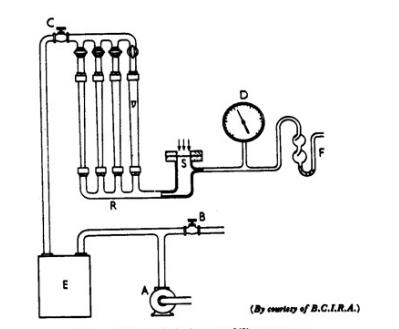
Air permeability is measured by Qinsun Auto Air Permeability Test Apparatus .This apparatus consists of the following parts:
Suction pump – A
By-pass valve – B
Series valve – C
Draught gauge – D
Reservoir – E
Safety valve – F
Rota meter – R
Specimen – S
Test Procedure:
Suction pump ‘A’ draws air through the test specimen ‘S’ at 20±2oC and 65±2% R.H. The rate of flow is controlled by the by – pass valve ‘B’ and the series valve ‘C’.
The rate of flow is adjusted until the required pressure drop across the fabric is indicated on a draught gauge ‘D’ which is graduated from 0 to 25 head of water.
‘E’ is a reservoir which smoothens out any disturbance due to varying velocities of the streams of air drawn through the various paths by the pump.
When the required pressure drop, which is normally 1 cm of water, is attained and the indicator of the draught gauge is steady, the rate of air flow is read off one the four Rota meters ‘R’, selected according to the permeability of the test specimen.
The Rota meters are calibrated, at 20oC and 760 mm of mercury to indicate air flow in cm3/sec and they cover the following ranges :
R1: 0.05-0.5
R2: 0.5-3.5
R3: 3-35
R4: 30 – 350
The test is commenced with R4 open and the other Rota meters closed. If the flow is less than 30 cm3/sec, R3 is opened and R4 closed.
This procedure is repeated until the most suitable range for the fabric under test has been selected.
To prevent damage to the draught gauge a safety valve F is provided.
The test area is 5.07 cm2 and from the readings on the Rota meter either the air permeability or the resistance can be calculated.
The average rate of flow from five specimens is calculated .
The results can be obtained by using the formula
Previous: What is Light Fastness Testing?
N e x t : Measure The Quality Of Textile Products
