

Search keywords:
product name, product type, model number,
test method, manufacturer, technique, application
-
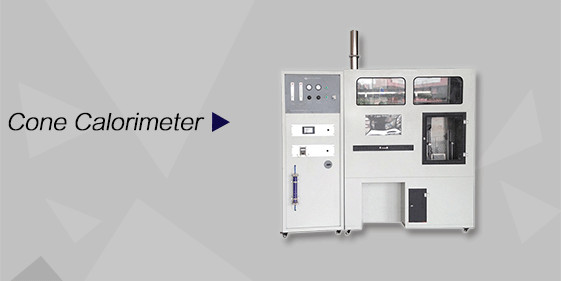
Cone Calorimeter
The import of American VTEC, cone calorimeter ultra high cost performance
more
-
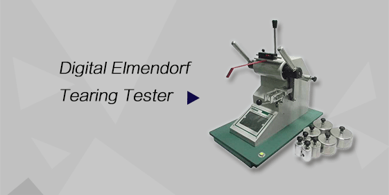
Digital Elmendorf Tearing Tester
Pendulum method test material tear strength, operating more simple, more accurate data
more
-
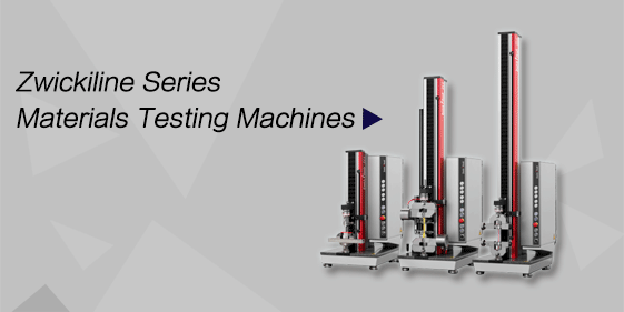
ZwickiLine Materials testing machines
Top of the world's leading universal material testing machine
more
Fabric Anti-Electromagnetic Radiation Performance Tester
BACK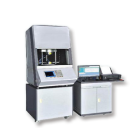

Standards:
Applications:
This tester is widely used for:
Evaluating shielding performance of electromagnetic shielding fabrics for garments and protective materials.
Testing coatings, conductive films, and metal meshes for electronics, aerospace, and automotive applications.
Assessing absorptive and reflective properties of planar materials against electromagnetic waves.
Research and development of EMI/EMC compliant textiles and composite materials.
Quality control in textile manufacturing and material certification labs.
Product Information:
The Fabric Anti-Electromagnetic Radiation Performance Tester is a precision instrument designed to measure the electromagnetic shielding effectiveness of various materials, including textiles, plastic sheets, metal foils, coatings, platings, conductive films, metal meshes, conductive glasses, and conductive medium plates. The tester employs the coaxial test method, providing high accuracy and reliable results for full-frequency, list, and point-frequency measurements.
Standards
GB/T 23326 – Electromagnetic shielding textile test standard (China)
GB/T 25471 – Electromagnetic shielding material testing method (China)
ASTM D4935 – Standard test method for measuring the electromagnetic shielding effectiveness of planar materials using a coaxial transmission line
SJ2054 – Coaxial method for conductive materials (China)
Features
(1) Uses coaxial test method, ensuring high transmission characteristics and testing accuracy.
(2) Supports full-frequency scanning, list scanning, and point-frequency measurements.
(3) Automatic control of signal emission and reception, data collection, curve display, and micro-printer output.
(4) Evaluates both absorption and reflection performance of planar materials.
(5) RS232 interface for computer connection, curve display, data analysis, and storage.
(6) USB interface for mobile data storage via flash drives.
(7) User-friendly interface with automated measurement and data processing.
Technical Parameters
1. Signal Source
| Parameter | Specification |
|---|---|
| Frequency Range | 300 KHz – 3000 MHz |
| Frequency Stability | ≤ ±5×10⁻⁶ |
| Frequency Resolution | 1 Hz |
| Signal Purity | ≤ -65 dBc/Hz (10 KHz offset) |
| Output Level | -45 dBm – +10 dBm |
| Level Accuracy | ±1.5 dB |
| Harmonic Suppression | ≥30 dB (1 MHz–3 GHz), ≥25 dB (300 KHz–1 MHz) |
| Directivity | ≥50 dB |
| Power Scanning | -8 dBm – +5 dBm |
| System Impedance | 50 Ω |
2. Receiver
| Parameter | Specification |
|---|---|
| Frequency Range | 300 KHz – 3000 MHz |
| Resolution Bandwidth | 100 Hz – 20 KHz |
| Dynamic Range | ≥95 dB (RBW = 1 KHz) |
| Maximum Input Level | +10 dBm |
| Input Damage Level | +20 dBm (DC +25V) |
| Standing Wave Ratio | ≤1.2 |
3. Phase Characteristics
| Parameter | Specification |
|---|---|
| Phase Resolution | 0.01° |
| Phase Trajectory Noise | 0.5° @ RBW 1 KHz; 1° @ RBW 3 KHz |
4. Transmit and Receive Frequencies
| Parameter | Specification |
|---|---|
| Transmit Frequency | 20 MHz – 1.3 GHz |
| Transmit Frequency Drift | <1000 Hz |
| Minimum Hopping Interval | 1 MHz |
| Transmit Output Power | >13 dBm |
| Receive Power Dynamic Range | +5 dBm – -55 dBm |
| Receiver Power Accuracy | ±1 dB |
| Resolution | 0.01 dB |
| Receiver Frequency Test Range | 10 MHz – 3 GHz |
| Double-layer Shielding Effectiveness | >20 dB |
5. Specimen Dimensions
| Parameter | Specification |
|---|---|
| Circular Specimen | Diameter 180–200 mm |
| Square Specimen | 180×180 mm – 200×200 mm |
| Thickness | 0–5 mm |
6. Instrument Specifications
| Parameter | Specification |
|---|---|
| Working Environment | 0–40°C, 0–75% RH |
| Power Supply | AC 220V ± 30V, 50 Hz, 100 W |
| Dimensions | 70×50×75 cm (L×W×H, excluding computer) |
| Weight | Approximately 75 kg |
Accessories
Main unit (coaxial testing module)
Branded computer for data analysis
Branded printer for reports
RS232 and USB cables for data transfer
Test Procedures
Prepare specimen according to dimensions (circular or square).
Mount specimen in coaxial test holder.
Select measurement mode: full-frequency, list, or point-frequency.
Start the automated signal emission and reception cycle.
Observe shielding effectiveness curves on LCD or computer software.
Print results using the built-in micro-printer or export data via USB.
Repeat as needed for multiple specimens.
