

Search keywords:
product name, product type, model number,
test method, manufacturer, technique, application
-
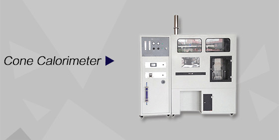
Cone Calorimeter
The import of American VTEC, cone calorimeter ultra high cost performance
more
-
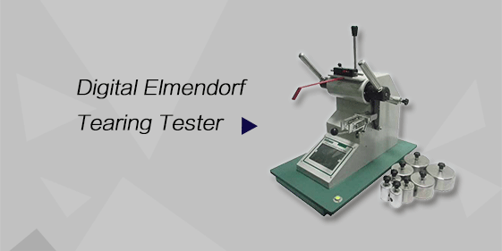
Digital Elmendorf Tearing Tester
Pendulum method test material tear strength, operating more simple, more accurate data
more
-
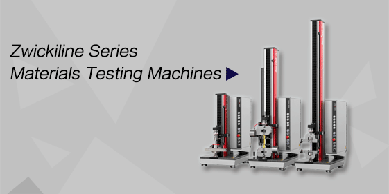
ZwickiLine Materials testing machines
Top of the world's leading universal material testing machine
more
High-Temperature Creep Testing Machine
BACK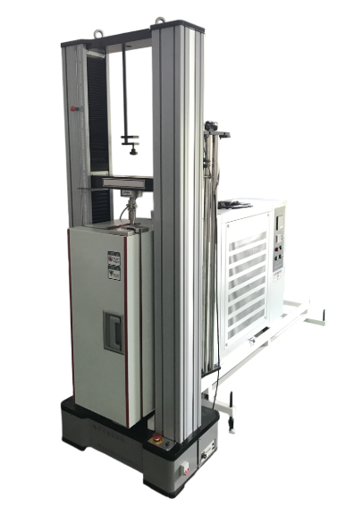

Standards:
Applications:
The testing machine is mainly used for creep, stress relaxation, tensile, compression, bending, shear, peel, and tear testing of non-metallic materials.
Product Information:
 Manufacturing and Inspection Standards
GB/T 16491 Electronic Universal Testing Machine
GB/T 2611 General Technical Requirements for Testing Machines
GB/T 6825.1 Verification of Static Uniaxial Testing Machines – Part 1: Verification and Calibration of the Force Measuring System of Tension and/or Compression Testing Machines
 Applicable Test Method Standards
ASTM D 2990 Standard Test Methods forTensile, Compressive, and Flexural Creep and Creep-Rupture of Plastics1
GB 11546.1-2008 Plastics — Determination of Creep Properties — Part 1: Tensile Creep
GB/T 15048-94 Rigid Cellular Plastics — Test Method for Compressive Creep
GB/T 20672-2006 Rigid Cellular Plastics — Determination of Compressive Creep under Specified Load and Temperature Conditions
GB/T 1040.1-2006 Plastics — Determination of Tensile Properties — Part 1
GB/T 1041-92 Test Method for Compressive Properties of Plastics
GB/T 9341-2000 Test Method for Flexural Properties of Plastics
Main Technical Specifications
Test Force
Maximum test force (kN): 10
Effective measuring range: 0.4%–100% FS (single range, no internal division)
Resolution: 1/300000
Relative indication error: ±0.5%
Test Speed
Speed adjustment range: 0.05–500 mm/min (stepless speed regulation)
Speed relative error: ±0.5%
Constant test force rate and constant deformation rate control range: 0.01%–5% FS/s
Constant test force rate and deformation rate control error: ±0.5%
Constant test force and constant deformation control range: 0.5%–100% FS
Constant test force and constant deformation control error:
Less than 10% FS: ±1% of the set value
Greater than 10% FS: ±0.1% of the set value
Displacement (Moving Crosshead)
Measurement range: 0–999 mm
Resolution: 0.001 mm
Relative indication error: ±0.5%
Deformation
Crosshead deformation measurement accuracy: ±0.5%
Crosshead deformation measurement range during test: 860 mm
Large deformation measurement accuracy: ±0.5%
Large deformation measurement range: 25–1000 mm
 Main Frame and Accessories
|
Model |
10 kN |
|
Maximum Test Force |
10 kN |
|
Effective Test Width |
420 mm |
|
Maximum Travel of Moving Crosshead |
1160 mm |
|
Main Frame Dimensions (L × W × H) |
900 × 480 × 1810 mm |
|
Maximum Clamping Force of Wedge Grips |
10 kN |
|
Clamping Range (Flat Specimen) |
0–8 mm |
|
Clamping Range (Round Specimen) |
Φ6–Φ16 mm |
|
Compression Device |
Φ70 mm |
|
Bending Device Support Roller Radius |
R2.5 / R5.0 mm |
|
Pressure Roller Diameter |
Φ5 mm |
|
Span Range |
120 mm |
|
Power Supply |
220 V, 50 Hz, 0.4 kW |
|
Weight |
280 kg |
Structural Principle and Performance Features
The computer-controlled electronic universal testing machine mainly consists of the main frame, fully digital measurement system (load, displacement, deformation), servo system, computer control system with software package, and functional accessories.
Main Frame
The upper crosshead and the worktable are connected by four columns forming a portal-frame structure. A transmission mechanism is installed at the bottom of the worktable.
The transmission of the AC servo motor is reduced through a three-stage circular synchronous belt pulley system, which drives the ball screw to rotate and move the crosshead up and down. In addition to the ball screw guidance, guide columns also provide guidance for the moving crosshead. Thus, the simply supported beam structure of the moving crosshead becomes a fixed beam structure, increasing the rigidity by nearly three times.
The circular synchronous belt pulley and ball screw pair provide stable backlash-free transmission, enabling precise control of test force and deformation speed.
A photoelectric encoder is installed at the upper end of the screw for displacement detection of the moving crosshead. A limit mechanism is installed on the left cover plate to limit the movement range of the moving crosshead.
Speed control adopts an imported fully digital AC servo system. Through high-precision feedback, a full closed-loop control is formed. The system features a wide speed regulation range, fast response, and short positioning time. It also provides test force and deformation rate control functions.
The worktable, moving crosshead, and upper crosshead are all manufactured from high-quality steel plates through precision machining, which reduces vibration when the specimen fractures and improves overall rigidity.
 Main Frame Features
The main frame adopts a portal-type prestressed structure with high rigidity, minimizing the influence of machine deformation on test results.
Circular synchronous belt pulley reduction and ball screw pair transmission are used to achieve backlash-free transmission, ensuring precise control of test force and deformation speed.
Stable transmission, fast response, and low noise.
Photoelectric encoder displacement sensor with high resolution and strong anti-interference capability.
Displacement protection system ensuring safe and reliable operation.
During assembly of the main frame and grips, strict control and adjustment are applied to ensure the coaxiality between the center hole of the load sensor on the moving crosshead and the positioning hole of the grip seat, as well as the coaxiality between the grip mounting shaft and the jaws. This ensures that the force application axis of the grips coincides with that of the testing machine, with an error controlled below 9%, which is far lower than the requirement of Grade 0.5 accuracy specified in GB/T 16491.
