

Search keywords:
product name, product type, model number,
test method, manufacturer, technique, application
-
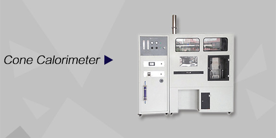
Cone Calorimeter
The import of American VTEC, cone calorimeter ultra high cost performance
more
-
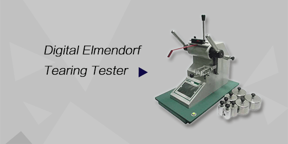
Digital Elmendorf Tearing Tester
Pendulum method test material tear strength, operating more simple, more accurate data
more
-
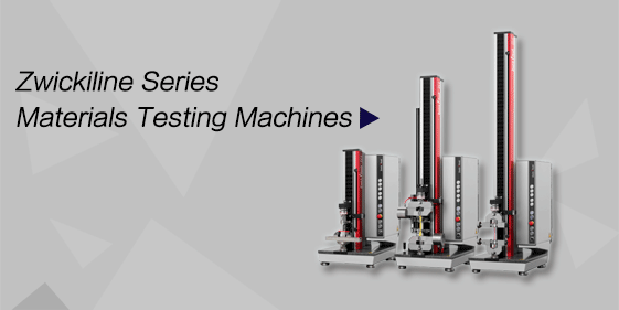
ZwickiLine Materials testing machines
Top of the world's leading universal material testing machine
more
Tapered Bearing Fatigue and Wear Testing Machine
BACK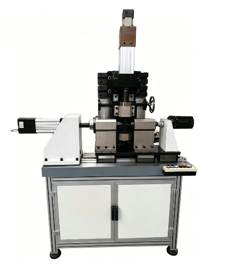

Standards:
Applications:
Product Information:
The tapered bearing fatigue and wear testing machine is a dedicated test equipment designed and manufactured according to user-supplied technical requirements.The system adopts a servo control system. Axial and radial loading are both driven by electric cylinders. Rotation is driven by a servo motor. The electrical system is controlled by a computer-based servo control system. The test software is developed in the Windows platform using Visual Studio (VS) programming language.The system can perform parameter setting, data acquisition and processing, real-time interface display, and curve plotting functions.
 Structure and Working Principle
The rotary (or oscillating) drive unit is installed on the base platform. It consists of a servo motor, gearbox, bearing support, coupling, torque sensor, etc.
The servo motor is equipped with an optical encoder for measuring and controlling rotational angle. The bearing support is used to install and support the test bearing, torque sensor, and motor. The inner bore shaft of the test bearing is connected to the rotary system through a universal coupling.
To eliminate the influence of misalignment during radial loading, a telescopic spline shaft is integrated into the rotary axis. A torque sensor is installed in the rotary system to measure torque.
The axial loading system consists of an electric loading cylinder, force sensor, loading linkage, and bearing support frame. The electric cylinder drives a loading frame supported by dual linear guide rails. Load is applied to the test bearing through a force sensor and linkage system.
To ensure smooth and impact-free loading, a set of double-stacked disc springs is integrated into the loading system. The load is transmitted to the test bearing through the disc springs. A coaxial swingable bearing seat is adopted to eliminate angular deviation during testing.
The radial loading system consists of an electric cylinder, force sensor, and loading bearing support. The cylinder is hinged to the base and applies radial load through the force sensor and support assembly. The encoder of the servo motor is used to measure displacement, and the deviation angle is calculated accordingly.
The test bearing fixture consists of a split bearing housing and replaceable test tooling. According to different bearing sizes, corresponding fixtures are selected and installed in the housing, then fixed by bolts. The test shaft is connected to the axial loading mechanism via bolts, and connected to the radial loading system and rotary system through a shaft and coupling, ensuring both easy installation and stable loading performance.
Main Technical Specifications
|
Item |
Parameter |
Value |
|
1 |
Axial & radial loading mode |
Alternating load (reversible direction) |
|
2 |
Axial loading capacity |
15 kN |
|
3 |
Radial loading capacity |
30 kN |
|
4 |
Sensor accuracy |
≤ ±1% (automatic range switching) |
|
5 |
Swing angle range |
±360° |
|
6 |
Angle measurement accuracy |
0.1° |
|
7 |
Control mode |
Angle / Force |
|
8 |
Operating frequency |
0–1.5 Hz (based on ±60° swing angle) |
|
9 |
Maximum bearing outer diameter |
≤ φ150 mm (customizable) |
|
10 |
Maximum rotational speed |
0–3000 rpm |
Technical Documents
General assembly drawing – 1 set
Wear parts, spare parts, and fixture drawings – 1 set
Electrical schematic, servo control schematic, and software system manual – 1 set
Operation manual – 1 copy
Packing list – 1 copy
Certificates of main purchased components – 1 set
Product certificate – 1 copy
 Main Configuration of Test System
|
Section |
No. |
Name |
Quantity |
Unit |
|
Main Machine Unit
|
1 |
Main frame (aluminum profile & worktable plate) |
1 |
Set |
|
2 |
Axial & radial loading mechanisms |
2 |
Sets |
|
|
3 |
Rotary loading mechanism |
1 |
Set |
|
|
4 |
Linear guide rails |
2 |
Pairs |
|
|
5 |
Coupling assembly |
1 |
Set |
|
|
6 |
Test fixture |
1 |
Set |
|
|
Control & Measurement Unit
|
1 |
Electric cylinders |
2 |
Units |
|
2 |
Servo motors & servo drives |
3 |
Sets |
|
|
3 |
Gear reducers |
3 |
Units |
|
|
4 |
Servo control system |
1 |
Set |
|
|
5 |
Servo drive system |
1 |
Set |
|
|
6 |
Load sensors |
2 |
Pcs |
|
|
7 |
Load amplifier |
2 |
Sets |
|
|
8 |
Torque amplifier |
1 |
Set |
|
|
Computer Control Unit |
1 |
High-voltage control system |
1 |
Set |
|
2 |
Computer & printer |
1 |
Set |
|
|
3 |
Encoder counting card |
1 |
Pc |
|
|
4 |
I/O card |
1 |
Pc |
|
|
5 |
A/D conversion card |
1 |
Pc |
|
|
6 |
Test software |
1 |
Set |
|
|
7 |
Shielded cables, wiring, solenoids, etc. |
Several |
— |
