

Search keywords:
product name, product type, model number,
test method, manufacturer, technique, application
-
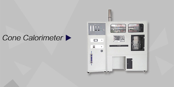
Cone Calorimeter
The import of American VTEC, cone calorimeter ultra high cost performance
more
-

Digital Elmendorf Tearing Tester
Pendulum method test material tear strength, operating more simple, more accurate data
more
-
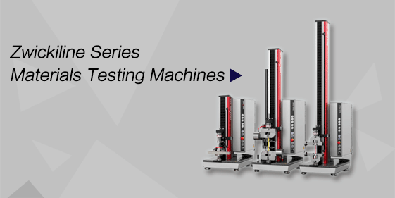
ZwickiLine Materials testing machines
Top of the world's leading universal material testing machine
more
Computer-Controlled Voltage Breakdown Tester
BACK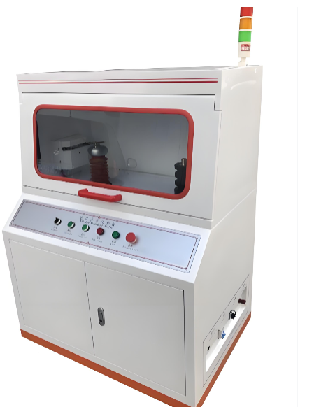

Standards:
Applications:
Product Information:
Compliance Standards
GB/T 1408-2006 — Test Method for Electric Strength of Insulating Materials
GB/T 1695-2005 — Test Method for Power Frequency Breakdown Strength and Withstand Voltage Strength of Vulcanized Rubber
GB/T 3333 — Test Method for Power Frequency Voltage Breakdown of Cable Paper
HG/T 3330 — Test Method for Breakdown Strength of Insulating Varnish Films
GB/T 12656 — Test Method for Power Frequency Voltage Breakdown of Capacitor Paper
ASTM D149 — Standard Test Method for Dielectric Breakdown Voltage and Dielectric Strength of Solid Electrical Insulating Materials at Commercial Power Frequencies
Scope of Application and Functions
This instrument is mainly used for testing the breakdown strength and withstand voltage performance of solid insulating materials under power frequency voltage or DC voltage conditions.
Applicable materials include: plastics, rubber, laminated materials, films, resins, mica, ceramics, glass, insulating varnishes, and various insulating components.
System Configuration
Control Module
This instrument is controlled by PC host software and is a new third-generation dielectric strength testing device independently developed by our company. The core control system is based on Siemens PLC control. The data acquisition section is completed by a Siemens digital integrated module, and communication between the system and the computer is carried out via an opto-isolated data cable, effectively eliminating electromagnetic interference during the testing process. Voltage and current measurements are performed using high-precision sensors.
Voltage Regulation Module
This module is mainly used for voltage regulation and allows adjustment of the voltage ramp rate. It is equipped with high-voltage zero-return limit and high-voltage step-up limit functions. The main hardware components include a voltage regulator and a motor system.
The software is user-friendly and capable of real-time display of the voltage rise curve and leakage current dynamic curve. The voltage ramp rate is continuously adjustable, allowing users to set the desired ramp speed to achieve smooth and accurate voltage increase. The system automatically stops testing after breakdown occurs, automatically records test results, displays test data, and provides accurate judgment. Test data can also be saved, analyzed, and printed.
High Voltage Module
This module primarily uses a high-voltage generator to increase the voltage from a low level according to a preset ramp rate. The core components consist mainly of a transformer and supporting anti-interference accessories.
Test Module
This section mainly consists of supporting test electrodes, a test oil tank, and a test support frame. It can also be operated in a high-temperature test environment according to user requirements.
Software Functions
01. Software Platform
WINDOWS-based operating platform with an intuitive user interface for convenient operation.
02. Curve Display
Real-time dynamic display of test curves during the testing process.
Dedicated to Innovation for Over Ten Years — Delivering Higher Quality
Professional Excellence Comes from Focus
Carefully manufacturing every instrument and taking responsibility for product quality to ensure worry-free use.
03. Data Export
Test results can be exported to Excel.
04. Test Report
Users can customize report names and print test reports.
05. Test Modes
Flexible selection between DC testing and AC testing.
06. Test Methods
Users can select among:
Breakdown Voltage Test
Withstand Voltage Test
Gradient Test
07. Parameter Settings
Flexible parameter configuration according to different test modes and methods.
08. Sample Settings
Flexible configuration of specimen parameters according to different testing standards.
09. Continuous Operation
During continuous testing, users can terminate the current test directly in the software and proceed to the next test.
10. Test Status Monitoring
Real-time display of testing status, including:
Safety door status
Voltage ramp indication
Zero-return reset indication
Other system operation indicators
Technical Requirements
|
No. |
Item |
Parameters |
Remarks |
|
|
Equipment Model |
DDJ-10KV / DDJ-20KV / DDJ-50KV |
|
|
01 |
Electrical Capacity |
1 KVA / 2 KVA / 3 KVA |
|
|
02 |
Output Voltage |
AC/DC–10KV / AC/DC–20KV / AC/DC–50KV |
|
|
03 |
Input Voltage |
AC–220V / 50Hz |
|
|
04 |
Voltage Ramp Rate |
0.1 KV/s–5 KV/s |
Manually Adjustable |
|
05 |
Voltage Rise Mode |
Constant Ramp / Step Ramp / Withstand Voltage Test |
|
|
06 |
Breakdown Stop Condition |
Voltage Trigger Stop / Current Trigger Stop |
|
|
07 |
Test Medium |
Air Test / Oil Bath Test / High-Temperature Test |
High Temperature Optional |
|
08 |
Data Acquisition |
Photoelectric Isolation Communication, Strong Anti-Interference Capability |
|
|
09 |
Voltage Accuracy |
≤1.5% |
|
|
10 |
Leakage Current |
0–100 mA |
Sensor Range |
|
11 |
Voltage Sensor |
0–100 V |
Sensor Range |
|
12 |
Electrode Specification |
Sheet Electrodes: φ25 mm × 2. φ75 mm × 1 |
Custom Electrode Available |
|
13 |
Discharge Method |
Automatic Electric Discharge |
|
|
14 |
Electrode Movement |
Manual Placement / Automatic Lifting |
Automatic Lifting Optional |
|
15 |
Test Oil Tank |
L × W × H: 300 × 150 × 200 mm |
Equipped with Floating Support for Easy Sample Replacement |
|
16 |
Test Illumination |
Built-in Lighting System |
|
|
17 |
Exhaust System |
Built-in Exhaust Fan |
|
|
18 |
Test Indication |
Integrated Multi-Color Tower Light for Test Status Indication |
|
|
19 |
Test Door |
Pneumatic Test Door / Sliding Door |
Sliding Door for Automatic Electrode Lifting Version |
|
20 |
Safety Protection |
Overvoltage Protection / Overcurrent Protection / Short Circuit Protection / Leakage Protection |
|
|
21 |
Operating Environment |
Room Temperature, Humidity ≤65% |
|
|
22 |
Main Unit Dimensions |
L × W × H: 1000 × 700 × 1400 mm |
|
|
23 |
Test Chamber Dimensions |
L × W × H: 1000 × 500 × 550 mm |
|
|
24 |
Observation Window |
Glass Window Size: 800 × 300 mm |
Large Viewing Window for Easy Observation |
|
25 |
Equipment Weight |
Approx. 150 kg |
