




Search keywords:
product name, product type, model number,
test method, manufacturer, technique, application
-
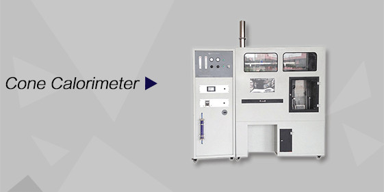
Cone Calorimeter
The import of American VTEC, cone calorimeter ultra high cost performance
more
-
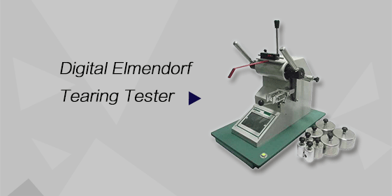
Digital Elmendorf Tearing Tester
Pendulum method test material tear strength, operating more simple, more accurate data
more
-
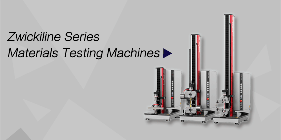
ZwickiLine Materials testing machines
Top of the world's leading universal material testing machine
more
200T Constant Load Manual Screw Press
BACK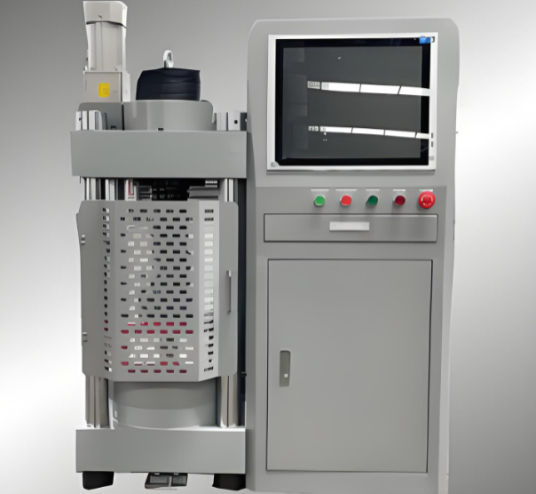


Standards:
Applications:
Product Information:
The system adopts a high-precision digital servo valve and features force closed-loop control function. It can achieve constant load rate loading with high control accuracy and excellent reliability. The system fully complies with the requirements of GB, ISO, ASTM and other standards for testing cement, concrete, and other materials. It is especially suitable for long-duration testing applications.
System Components
Microcomputer-controlled electro-hydraulic measurement and control unit
Pressure sensor
Digital servo valve
Pressure reducing valve
Technical Performance Specifications and Parameters
Maximum Load: 2000 kN
Rated Working Voltage:
Control system: AC 220V ±10%
Main machine: AC 380V ±10%
Relative Error of Indication Repeatability: ≤ ±1%
Measurement Accuracy Range: 4%–100% FS
Constant Load Rate Control Range: 4–100% FS/min
Instrument Fuse: 1A
Maximum Distance Between Compression Plates: 320 mm
Dimensions of Upper and Lower Compression Plates: Φ240 mm
Piston Diameter × Maximum Stroke: 250 × 50 mm
Distance Between Columns: 280 mm
Motor Power: 0.75 kW
Input Voltage: 380V
Overall Dimensions (L × W × H): 950 × 400 × 1300 mm
Net Weight: Approx. 650 kg
Structural Description
The testing machine mainly consists of three parts: the main frame, hydraulic control unit, and load measuring instrument.
Main Frame Section
The main frame of the testing machine is composed of four columns that connect the cylinder body with the upper crossbeam. An adjustment screw is installed on the upper crossbeam of the testing machine. The testing space height can be manually adjusted. A ball seat and upper compression plate are installed at the lower end of the screw.
The lower compression plate is mounted on the piston of the hydraulic cylinder. When the specimen contacts the upper compression plate, the ball seat of the upper compression plate can automatically
adjust its position to maintain balance, ensuring that the specimen and the upper compression plate remain level.
Calibration lines for specimen positioning are engraved on the lower compression plate. During testing, the specimen should be aligned with these calibration lines.
A dust-proof cover is installed beneath the lower compression plate to prevent or reduce dust entering the hydraulic cylinder during piston movement, thereby avoiding damage to the cylinder body or oil seal.
A sealing device is installed between the piston and the hydraulic cylinder to prevent oil leakage. However, during operation, if a small amount of oil leakage occurs from the piston, an annular oil groove is provided at the top of the cylinder body, with an oil drainage channel to discharge the leaked oil back into the main oil tank.
Hydraulic Control Section
The control unit of this testing machine mainly consists of an oil tank, oil pump, oil filter, electric motor, and a fully automatic digital constant loading system.
The oil pump is a direct-drive axial five-piston pump.
System Function Section
For detailed information about system functions, please refer to the Pressure Testing Machine Measurement and Control Software.
Maintenance and Care
The testing machine should be installed in a clean, dry environment with a uniform temperature, free from vibration and corrosive gases.
The testing machine should be kept clean. Parts without protective coating on the surface of the machine should be regularly wiped with oil to prevent rust and corrosion.
The recommended hydraulic oil specification is No. 46 anti-wear hydraulic oil.
The rising position of the testing machine piston must not exceed 50 mm. A limit position marking device is installed on the hydraulic control unit of the testing machine. When the arrow reaches the limit position, click the valve reset button on the software interface to lower the piston before restarting the motor for the next test.
Calibration of the Testing Machine
The testing machine should be calibrated once a year.
The calibration of the testing machine should be carried out under the following conditions:
Ambient temperature: within the range of 20 ± 10℃.
Relative humidity: ≤ 80%.
Environment: free from vibration.
Power supply voltage fluctuation: not exceeding ±10% of the rated voltage, with relatively stable voltage.
After connecting the power supply, preheat the machine for 30 minutes, then perform zero adjustment according to the operating instructions.
Start the motor and repeatedly apply the maximum load three times. After that, adjust the load display back to the zero point and begin the calibration process.
