

Search keywords:
product name, product type, model number,
test method, manufacturer, technique, application
-
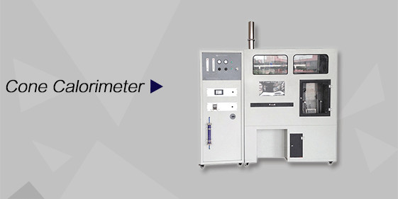
Cone Calorimeter
The import of American VTEC, cone calorimeter ultra high cost performance
more
-
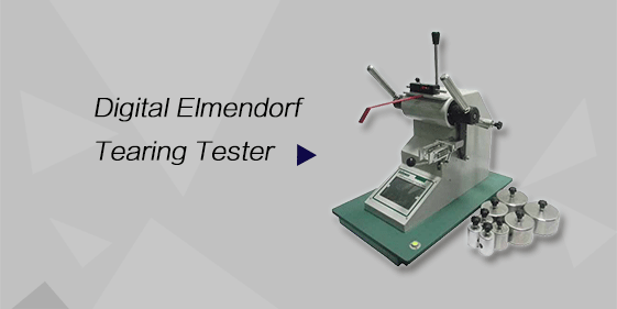
Digital Elmendorf Tearing Tester
Pendulum method test material tear strength, operating more simple, more accurate data
more
-
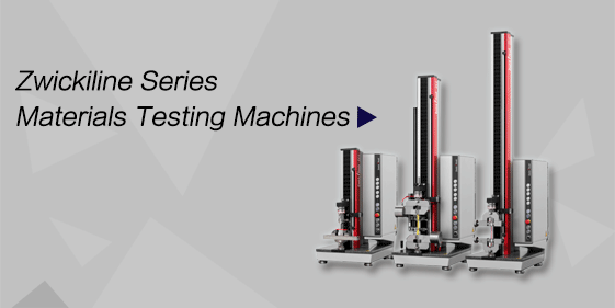
ZwickiLine Materials testing machines
Top of the world's leading universal material testing machine
more
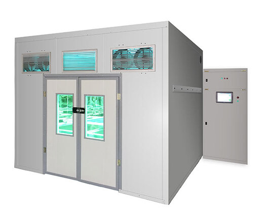
Ultraviolet Aging Test Chamber
BACK
Standards:
(1)IEC 61215 Terrestrial Photovoltaic (PV) Modules – Design Qualification and Type Approval (2)IEC 61646 Thin-Film Terrestrial Photovoltaic (PV) Modules – Design Qualification and Type Approval
Applications:
Ultraviolet aging performance evaluation of complete photovoltaic modules
UV resistance testing of photovoltaic glass, backsheet, EVA, POE, and other encapsulation materials
Reliability type testing and factory consistency verification of photovoltaic modules
Accelerated ultraviolet aging tests during the research and development of new photovoltaic structures and materials
Testing services for third-party photovoltaic inspection and certification laboratories
Ultraviolet aging research for outdoor electrical equipment and optical materials
Product Information:
Ultraviolet Aging Test Chamber is a laboratory testing system specifically designed for photovoltaic module ultraviolet preconditioning. The chamber simulates long-term outdoor exposure of photovoltaic modules to solar ultraviolet radiation, reproducing UV-induced material aging effects under controlled conditions. By accelerating natural ultraviolet exposure in a laboratory environment, the equipment enables evaluation of ultraviolet aging impacts that would normally take months or years outdoors, supporting verification of UV resistance and structural reliability of photovoltaic modules and encapsulation materials.
Parameters
| Item | Technical Specification |
|---|---|
| Structural material | High UV-blocking, high-sealing, high-thermal-insulation specialized material |
| Total UV irradiation area | ≥2000 mm × 2000 mm |
| Maximum test capacity | Simultaneous testing of 2 photovoltaic modules (2 m × 1 m each) |
| Light source type | Xenon lamp |
| Lamp lifetime (single set) | Approx. 1000 h |
| Spare lamps | 1 set (standard configuration) |
| System cumulative service life | ≥2000 h |
| UVA / UVB energy ratio | UVB accounts for approx. 3%–10% of total energy |
| Irradiance intensity | Approx. 100 W/m² in the 280–385 nm range |
| 280–320 nm proportion | ≤10% |
| Irradiance uniformity | Better than ±15% |
| UVA probe | 320–385 nm, fiber-optic type |
| UVB probe | 280–320 nm, fiber-optic type |
| Module surface temperature | 60 ℃ ±5 ℃ |
| Temperature resolution | 0.1 ℃ |
| Temperature measurement accuracy | ±0.1 ℃ |
| Ozone generation | Negligible |
| Irradiation method | Top irradiation, light source vertically directed at module surface |
| Control mode | Touchscreen control with automatic monitoring and light source cut-off |
Features
Large irradiation area suitable for full-size photovoltaic module testing
Independent UVA and UVB dual-band monitoring compliant with IEC standard requirements
High irradiance intensity effectively shortens test duration
Precise irradiance uniformity control ensures consistency and comparability of test results
Real-time module surface temperature monitoring prevents non-UV-related thermal degradation
Extremely low ozone generation avoids additional material aging effects
Touchscreen human–machine interface enables intuitive parameter setting and traceable operation status
Accessories
(1)Xenon lamp set (standard configuration)
(2)UVA fiber-optic probe (320–385 nm)
(3)UVB fiber-optic probe (280–320 nm)
(4)High-precision surface temperature sensor
(5)Control system (touchscreen and control module)
(6)Dedicated power supply and connection components
Test Procedures
Confirm normal status of the light source, temperature sensors, and irradiance probes before testing
Install photovoltaic modules according to standard requirements, ensuring the irradiated surface is perpendicular to the light source
Set irradiance intensity, test duration, and module surface temperature
Start the ultraviolet aging test and monitor system parameters in real time
Keep the chamber door closed throughout the test to prevent ultraviolet leakage
If irradiance or temperature exceeds preset limits, the system automatically cuts off the light source
After test completion, allow modules to cool to a safe temperature before removal
Maintenance Information
Regularly inspect xenon lamps and replace them according to specified service life
Periodically calibrate UVA and UVB probes to ensure measurement accuracy
Check temperature sensors and control systems for stable operation
Keep the irradiation chamber clean to maintain irradiance uniformity
Verify sealing components to prevent UV leakage and ensure operator safety
Conclusion
The Ultraviolet Aging Test Chamber provides a controlled and accelerated method for evaluating ultraviolet aging effects on photovoltaic modules and encapsulation materials. With large irradiation capacity, precise UVA and UVB monitoring, stable temperature control, and high irradiance uniformity, the system supports reliable assessment of UV resistance and long-term performance stability. It is a key testing platform for photovoltaic product development, certification, and quality verification.
FAQ
What is the primary function of the Ultraviolet Aging Test Chamber for photovoltaic modules?
The chamber is designed to simulate long-term outdoor ultraviolet exposure under controlled laboratory conditions. By reproducing UVA and UVB radiation using a xenon light source and maintaining stable surface temperature, the equipment accelerates material aging processes. This allows evaluation of ultraviolet resistance, structural stability, and performance durability of photovoltaic modules and encapsulation materials without waiting for extended outdoor exposure periods.
Why are both UVA and UVB bands independently monitored during testing?
Independent monitoring of UVA and UVB bands ensures compliance with IEC standards and provides accurate control of spectral energy distribution. Since different photovoltaic materials respond differently to UVA and UVB radiation, precise monitoring helps prevent overexposure or underexposure in specific wavelength ranges, improving the reliability and repeatability of ultraviolet aging test results.
How does the chamber prevent non-ultraviolet factors from affecting test results?
The system continuously monitors module surface temperature and controls it within 60 ℃ ±5 ℃. If temperature or irradiance exceeds preset limits, the light source is automatically shut off. In addition, negligible ozone generation minimizes secondary chemical effects, ensuring that material degradation is primarily caused by ultraviolet radiation rather than thermal or oxidative factors.
