

Search keywords:
product name, product type, model number,
test method, manufacturer, technique, application
-
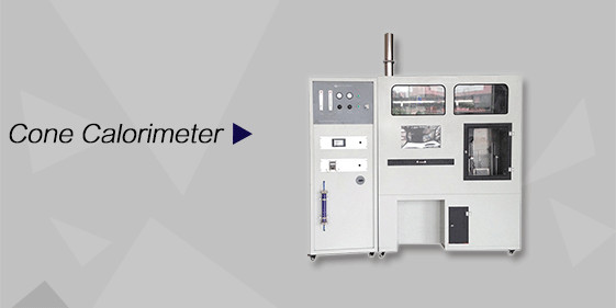
Cone Calorimeter
The import of American VTEC, cone calorimeter ultra high cost performance
more
-
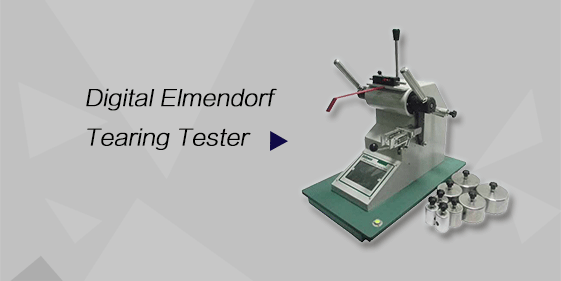
Digital Elmendorf Tearing Tester
Pendulum method test material tear strength, operating more simple, more accurate data
more
-

ZwickiLine Materials testing machines
Top of the world's leading universal material testing machine
more
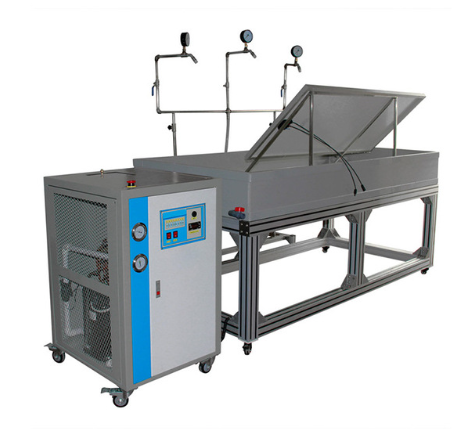
Wet Leakage Current Test System
BACK
Standards:
The Wet Leakage Current Test System is designed to meet the requirements of the following standards: (1) GB/T 9535 – Crystalline Silicon Terrestrial Photovoltaic (PV) Modules – Design Qualification and Type Approval (2) GB/T 20047 – Photovoltaic (PV) Module Safety Qualification Requirements (3) IEC 61215 – Terrestrial Photovoltaic (PV) Modules – Design Qualification and Type Approval (4) IEC 61730 – Photovoltaic (PV) Module Safety Qualification (relevant clauses on insulation and electrical safety)
Applications:
The system is suitable for electrical safety and insulation performance testing of photovoltaic modules in simulated wet environments, including:
Electrical insulation testing of crystalline silicon PV modules (monocrystalline and polycrystalline)
Wet leakage current evaluation of thin-film PV modules (CIGS, CdTe, a-Si, etc.)
Design qualification and type testing of photovoltaic modules
Routine quality control testing during PV module production
Reliability and safety performance verification of PV modules
Type approval testing in third-party testing institutes and certification laboratories
Insulation structure evaluation during PV module R&D
Photovoltaic safety performance research in universities and research institutions
Product Information:
The Wet Leakage Current Test System is a dedicated testing solution designed to evaluate the electrical insulation performance of photovoltaic (PV) modules under wet environmental conditions. By applying a specified withstand voltage to PV modules under controlled water temperature, water resistivity, and spray conditions, the system measures leakage current and insulation resistance. It is used to verify the safety and reliability of PV modules when exposed to rain, fog, dew, water immersion, or melting snow, ensuring compliance with photovoltaic safety and qualification requirements.
Parameters
| Item | Technical Specification |
|---|---|
| Test Tank Dimensions | 2100 × 1000 × 250 mm (W × D × H) |
| Tank Material | Acrylic (Organic Glass) |
| Tank Thickness | 15 mm |
| Water Temperature Control Range | 22 ± 3 ℃ |
| Temperature Control Method | Self-developed water constant-temperature system |
| Test Liquid Resistivity | ≤ 3500 Ω·cm |
| Spray Method | Multi-angle adjustable spray |
| Spray Nozzle Type | UL laboratory dedicated spray nozzles |
| Spray Water Pressure / Flow | Adjustable |
| Maximum Test Voltage | 0–5000 V (adjustable) |
| Leakage Current Limit | 5 mA |
| Voltage Ramp Rate | 500 V/s |
| Insulation Resistance Range | 1 MΩ – 9999 MΩ |
| Leakage Current Measurement Range | 0.001 – 5.000 mA (DC) |
Features
Fully compliant with wet leakage current test requirements specified in IEC 61215
Constant-temperature water tank ensures stable water temperature and high test repeatability
Controlled water resistivity guarantees consistency and comparability of test conditions
Multi-directional spray structure realistically simulates rain, condensation, and wet exposure
High-precision hipot tester provides accurate leakage current and insulation resistance measurements
High system integration, suitable for both type testing and batch inspection of PV modules
Robust structural design supports long-term and continuous laboratory operation
Accessories
(1) Dielectric Withstand Voltage Tester (0–5000 V output)
(2) Water Constant-Temperature System with independent control cabinet
(3) Acrylic Insulation Test Water Tank
(4) Adjustable Multi-angle Spray Frame
(5) UL Dedicated Spray Nozzles
(6) Conductivity Meter for monitoring water resistivity
(7) PV Module Sample Holder
(8) Test Water (configured according to resistivity requirements)
(9) Sensors and Probes (for periodic calibration or replacement)
Test Procedures
Prepare the test water according to standard requirements and adjust the resistivity.
Start the water temperature control system and stabilize the temperature at 22 ± 3 ℃.
Fix the photovoltaic module on the sample holder and complete electrical connections.
Activate the spray system to ensure uniform wetting of the module surface and frame.
Increase the test voltage at a controlled rate of 500 V/s until the specified value is reached.
Maintain the withstand voltage and measure leakage current and insulation resistance.
Record test results and determine compliance based on standard leakage current limits.
Maintenance Information
Regularly calibrate the dielectric withstand voltage tester and leakage current measurement system.
Periodically verify water resistivity and conductivity meter accuracy to maintain test consistency.
Inspect spray nozzles for blockage or wear to ensure uniform spraying performance.
Check temperature control system operation and sensors for long-term stability.
Replace consumable components such as sensors and probes according to calibration schedules.
Conclusion
The Wet Leakage Current Test System provides a reliable and standardized solution for evaluating the electrical insulation safety of photovoltaic modules under wet environmental conditions. With precise control of water temperature, resistivity, spray conditions, and test voltage, the system ensures accurate and repeatable measurement of leakage current and insulation resistance. It is well suited for design qualification, production quality control, certification testing, and photovoltaic safety research.
FAQ
1. What is the main purpose of the Wet Leakage Current Test System?
The Wet Leakage Current Test System is used to assess the electrical insulation performance and safety of photovoltaic modules under wet environmental conditions. By simulating rain, moisture, condensation, and water exposure with controlled water temperature and resistivity, the system applies a specified DC withstand voltage to the module. The resulting leakage current and insulation resistance are measured and compared with standard limits to determine whether the module can operate safely in humid or wet outdoor environments.
2. Which types of photovoltaic modules can be tested using this system?
The system supports both crystalline silicon photovoltaic modules, including monocrystalline and polycrystalline types, as well as thin-film photovoltaic modules such as CIGS, CdTe, and amorphous silicon. Its adjustable sample holder, spray configuration, and electrical parameters allow it to accommodate different module structures and sizes while maintaining compliance with relevant safety standards.
3. Why is water resistivity control important during wet leakage current testing?
Water resistivity directly affects the conductivity of the test environment and can significantly influence leakage current results. By controlling the resistivity of the test water to a specified value, the system ensures that all tests are conducted under consistent and repeatable conditions. This improves result comparability and ensures that measured leakage currents accurately reflect the insulation performance of the photovoltaic module rather than variations in water quality.
4. How does the system ensure test safety during high-voltage operation?
The system uses a controlled voltage ramp rate of 500 V/s to avoid sudden electrical stress that could cause flashover or damage. During testing, the module is fully isolated in the test tank, and operators are prohibited from direct contact with the sample or electrodes. These measures ensure safe and stable execution of high-voltage wet leakage current tests.
