

Search keywords:
product name, product type, model number,
test method, manufacturer, technique, application
-
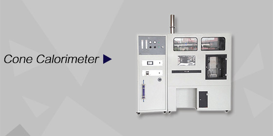
Cone Calorimeter
The import of American VTEC, cone calorimeter ultra high cost performance
more
-
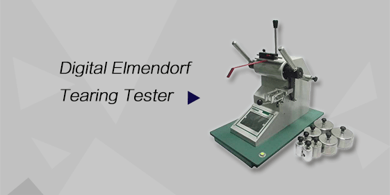
Digital Elmendorf Tearing Tester
Pendulum method test material tear strength, operating more simple, more accurate data
more
-
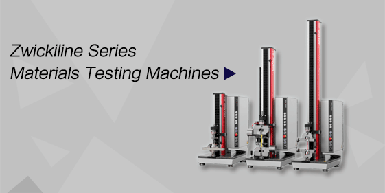
ZwickiLine Materials testing machines
Top of the world's leading universal material testing machine
more
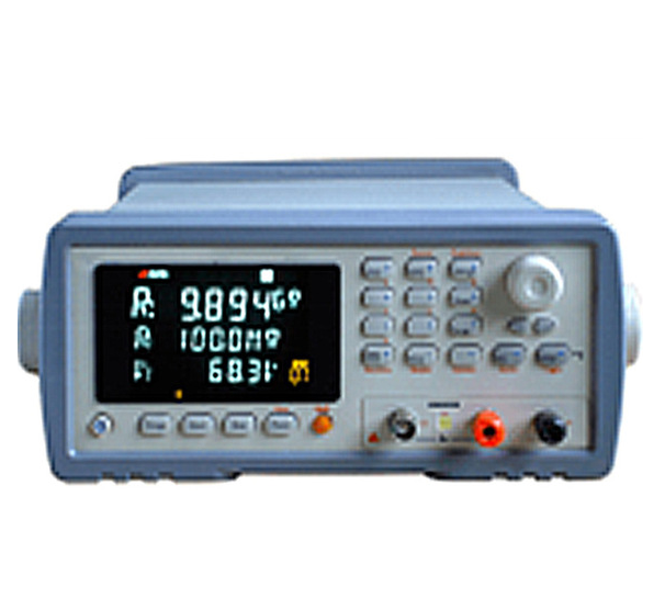
Photovoltaic Module Insulation Resistance chamber
BACK
Standards:
The tester is designed to comply with key national and international standards: (1) GB/T 9535 – Crystalline Silicon Terrestrial Photovoltaic (PV) Modules – Design Qualification and Type Approval (2) IEC 61215 – Terrestrial Photovoltaic (PV) Modules – Design Qualification and Type Approval
Applications:
The tester is applicable in various PV module testing scenarios:
Crystalline silicon PV module insulation performance evaluation
Thin-film PV module insulation resistance testing
Design verification and type testing of PV modules
Factory inspection and production process quality control
Re-measurement of insulation after damp-heat, wet-freeze, or aging tests
Third-party testing and certification laboratories
Electrical safety performance assessment during R&D of PV modules
Product Information:
The Photovoltaic Module Insulation Resistance Tester is a specialized instrument designed to evaluate the electrical insulation performance of photovoltaic (PV) modules. By applying a controlled DC test voltage between the conductive parts of the module and its frame or other exposed conductive parts, it measures insulation resistance and leakage current. This allows comprehensive assessment of module electrical safety and reliability under long-term operation and harsh environmental conditions, making it essential for type testing, design verification, and quality control.
Parameters
| Item | Technical Specification |
|---|---|
| Test Parameters | Insulation Resistance & Leakage Current |
| Insulation Resistance Range | 100 kΩ – 10 TΩ (10⁵ – 10¹³ Ω) |
| Basic Accuracy of Insulation Resistance | <1 GΩ: 1%; ≥1 GΩ: 3%; ≥10 GΩ: 5%; ≥1 TΩ: 10% |
| DC Test Voltage Output | 1.0 – 1000 VDC (negative polarity) |
| Voltage Step | <100 V: 0.1 V; ≥100 V: 1 V |
| Voltage Output Accuracy | 1% |
| Maximum Charging Current | 30 mA ± 5 mA |
| Range Selection | Six automatic/manual ranges |
| Test Speed | High: 55 times/s; Medium: 25 times/s; Low: 3 times/s |
| Timer Function | 0 – 999.9 s adjustable |
| Trigger Modes | Internal, Manual, External, Remote |
Features
Simultaneous measurement of insulation resistance and leakage current for comprehensive PV module safety assessment
Wide measurement range from kΩ to TΩ, suitable for various modules and testing stages
Continuously adjustable test voltage complying with IEC 61215 requirements
Built-in precise timing control for repeatable testing conditions
High-contrast VFD display showing multiple parameters simultaneously
Comparator function for rapid pass/fail evaluation of modules
Supports RS232C and SCPI commands for system integration and automated testing
Accessories
(1) Insulation resistance tester main unit with display and control system
(2) High-voltage test leads for module conductive parts
(3) Grounding test leads for module frame or exposed conductive parts
(4) Test fixture for connecting electrodes and frame
(5) RS232 communication cable for data transfer
(6) Optional handler interface for integration with sorting/automation systems
(7) Consumable high-voltage test leads for long-term replacement
Test Procedures
Ensure PV module surface is clean and dry to avoid measurement errors due to surface moisture.
Connect the module conductive terminals to the tester high-voltage output.
Connect the module frame or exposed conductive parts to ground.
Set test voltage, charging time, and measurement speed according to standard requirements.
Start the test to measure insulation resistance and leakage current.
Record results and evaluate pass/fail criteria.
After testing, release residual voltage before disconnecting test leads.
Maintenance Information
Regularly inspect and calibrate high-voltage leads and test fixtures to maintain measurement accuracy.
Ensure the VFD display and timing controls function properly before testing.
Periodically check test leads and replace them if insulation degradation occurs.
Clean tester surfaces and connectors to prevent contamination and ensure reliable electrical contact.
Verify that test settings align with applicable standards for consistent results.
Conclusion
The Photovoltaic Module Insulation Resistance Tester provides reliable, repeatable, and precise evaluation of PV module insulation performance. Its wide voltage range, synchronized leakage current measurement, and programmable timing enable accurate assessment of electrical safety under various operating and environmental conditions, supporting R&D, type testing, production quality control, and certification activities.
FAQ
1. What does the Photovoltaic Module Insulation Resistance Tester measure?
It measures insulation resistance and leakage current between the conductive parts of a PV module and its frame or exposed conductive parts. By applying a controlled DC voltage, it determines whether the module meets electrical safety standards, ensuring reliable performance under long-term operation and harsh environmental conditions.
2. What voltage range can the tester output?
The tester provides a DC voltage output from 1.0 V to 1000 V (negative polarity), adjustable continuously. This wide voltage range allows testing of different types of PV modules and ensures compliance with IEC 61215 insulation testing requirements.
3. How does the tester ensure accurate insulation resistance measurements?
Accuracy is maintained through stable voltage output, precise timing control, and a high-resolution measurement range from 100 kΩ to 10 TΩ. During testing, the instrument charges the circuit and measures leakage current, which is then converted to insulation resistance. Regular calibration of leads and fixtures also ensures measurement reliability.
