

Search keywords:
product name, product type, model number,
test method, manufacturer, technique, application
-
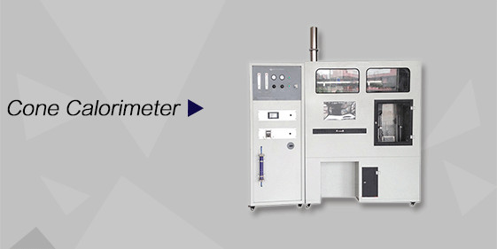
Cone Calorimeter
The import of American VTEC, cone calorimeter ultra high cost performance
more
-
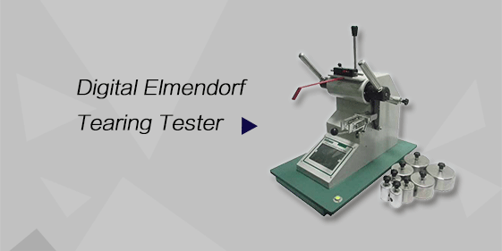
Digital Elmendorf Tearing Tester
Pendulum method test material tear strength, operating more simple, more accurate data
more
-
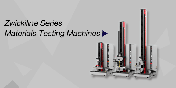
ZwickiLine Materials testing machines
Top of the world's leading universal material testing machine
more
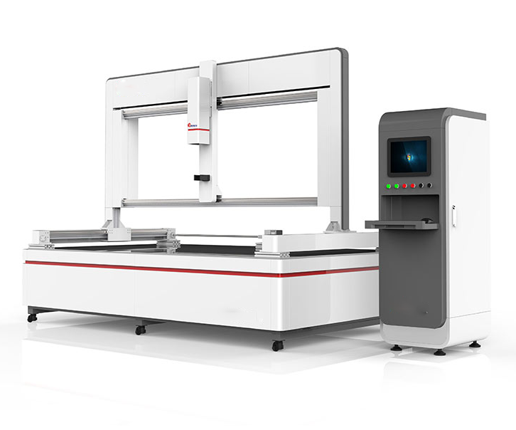
Hail Impact Test Machine
BACK
Standards:
The machine is designed to meet the following key standards: (1) GB/T 9535 – Crystalline Silicon Terrestrial Photovoltaic Modules – Design Qualification and Type Approval (2) IEC 61215 – Terrestrial Photovoltaic Modules – Design Qualification and Type Approval (3) IEC 61646 – Thin-Film Photovoltaic Modules – Design Qualification (4) UL 1703 – Standard for Safety of Photovoltaic Modules
Applications:
The Hail Impact Test Machine is suitable for a variety of testing and research scenarios:
Type testing and certification of PV modules
Factory inspection and quality control of PV modules
R&D evaluation of PV modules’ hail resistance
Impact durability testing of wind power and other photovoltaic building components
Climate simulation laboratories for mechanical impact studies
Safety and reliability assessment of solar PV systems
Product Information:
The Hail Impact Test Machine is a specialized laboratory device designed to evaluate the hail resistance of photovoltaic (PV) modules. By launching artificially prepared ice balls at controlled velocities toward the module surface, it simulates hailstorm conditions to assess mechanical impact resistance and structural reliability. The system provides precise positioning, speed measurement, and controlled impact, ensuring compliance with international standards for PV module type testing and certification.
Parameters
| Item | Technical Specification |
|---|---|
| Launch Device Power | Compressed air from air compressor |
| Air Pressure | 6 – 8 bar |
| Ice Ball Loading | Manual single-shot |
| Barrel Length | ~940 mm, replaceable |
| X-Axis Travel | ~2100 mm |
| Y-Axis Travel | ~1000 mm |
| Positioning Accuracy | ≤1 mm |
| Impact Area | 2000 × 1000 mm |
| Guidance | High-precision imported rails |
| Drive | Imported servo motor + synchronous belt |
| Position Control | Automated via upper computer |
| Ice Ball Speed Measurement | Infrared sensor captures flight time t, V=S/t |
| Speed Accuracy | ±5% |
| Speed Range | 0 – 50 m/s |
| Ice Ball Impact Speed | 25 mm: 23.0 m/s ±5%; 35 mm: 27.2 m/s ±5%; 45 mm: 30.7 m/s ±5% |
| Ice Ball Diameter Deviation | ≤5% |
| Ice Ball Weight Deviation | ≤5% |
| Ice Ball Preparation Temperature | -10℃ |
| Ice Ball Mold | Inner diameter precision <1%; 1 mold 6 balls, at least 2 sets; CNC machined, deformation-resistant material |
Features
Automated X/Y-axis positioning ensures precise ice ball impact on designated areas
High-precision infrared speed measurement system monitors real-time ice ball velocity
Simulates realistic hail diameters and impact speeds according to IEC and UL standards
Ice ball mold precision guarantees diameter and weight deviation ≤5%
Replaceable barrel design adapts to different ice ball sizes
Upper computer control executes automated impact sequences, enhancing repeatability and safety
Accessories
(1) Launch device – includes pneumatic system and barrel
(2) X/Y-axis positioning device – dual-axis servo system, rails, and control modules
(3) Ice ball speed measurement system – infrared sensor and data acquisition module
(4) Upper computer control system – automates impact and positioning
(5) Ice ball storage box – maintains low temperature storage
(6) Consumable ice ball molds – 1 mold 6 balls, at least 2 sets per size
(7) Consumable ice balls – 25. 35. 45 mm diameters, prepared as needed
(8) Optional replacement barrels – supports different calibers or worn barrel replacement
Test Procedures
Prepare ice balls according to standard and store in the low-temperature storage box.
Fix the PV module on the testing platform with the surface perpendicular to ice ball flight.
Configure the upper computer with ice ball size, impact speed, target location, and number of impacts.
Launch ice balls according to the set program.
After impact, measure PV module appearance and electrical parameters (short-circuit current, open-circuit voltage, etc.).
Compare results against IEC 61215. IEC 61646. and UL 1703 standards to determine pass/fail.
Automatically record and save test data for analysis and comparison.
Maintenance Information
Ensure ice ball storage box and module platform temperatures meet requirements before testing.
Inspect X/Y-axis rails, barrels, and molds regularly to maintain positioning precision.
Verify infrared speed sensors and data acquisition modules for accuracy.
Clean rails and control surfaces to prevent ice contamination or obstruction.
Check pneumatic systems and replace air filters periodically.
Inspect barrels and molds for wear or deformation before each experiment.
Conclusion
The Hail Impact Test Machine provides precise, reliable, and repeatable evaluation of PV module hail resistance. Automated positioning, high-accuracy speed measurement, and adjustable ice ball parameters allow realistic simulation of natural hail impact. It supports R&D, type testing, factory quality control, and certification labs, ensuring PV module safety, durability, and compliance with international standards.
FAQ
1. What is the main purpose of the Hail Impact Test Machine?
The Hail Impact Test Machine is designed to evaluate the impact resistance of photovoltaic modules against hail. By firing artificial ice balls at controlled speeds and diameters, it simulates hailstorm conditions to assess mechanical damage, module durability, and structural reliability under extreme weather conditions.
2. How are ice ball speeds controlled and measured?
Ice ball speeds are controlled using a pneumatic launch system powered by compressed air at 6–8 bar. A high-precision infrared sensor measures the flight time of the ice ball, calculating velocity as V=S/t. The system achieves a speed accuracy of ±5% and allows simulation of natural hail velocities across different diameters (25 mm, 35 mm, 45 mm).
3. What safety precautions are required during testing?
Operators must wear protective equipment to prevent injury from high-speed ice balls. No personnel should enter the impact zone during testing. Ice ball molds must be handled carefully to avoid breakage, and X/Y positioning and speed measurement systems must be calibrated before each experiment to ensure precision.
