

Search keywords:
product name, product type, model number,
test method, manufacturer, technique, application
-
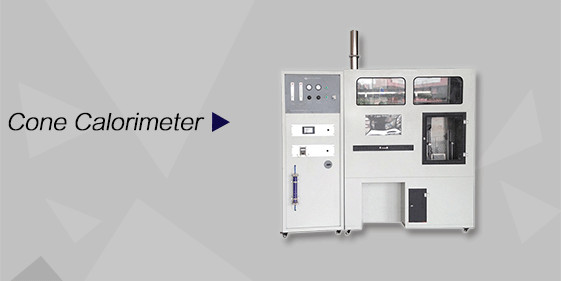
Cone Calorimeter
The import of American VTEC, cone calorimeter ultra high cost performance
more
-

Digital Elmendorf Tearing Tester
Pendulum method test material tear strength, operating more simple, more accurate data
more
-
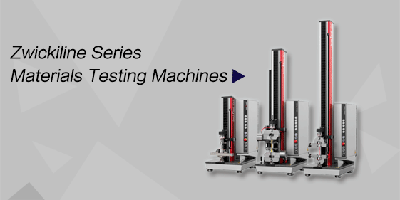
ZwickiLine Materials testing machines
Top of the world's leading universal material testing machine
more
Mechanical Load Testing Machine
BACK
Standards:
The machine is designed to meet key international and domestic PV module mechanical testing standards: GB/T 9535 series – Mechanical Load Testing of Photovoltaic Modules IEC 61215 – Crystalline Silicon Photovoltaic Module Design Qualification and Type Approval IEC 61646 – Thin-Film Photovoltaic Module Design Qualification IEC 62782 – Mechanical Load Testing for PV Modules under Snow and Wind UL 1703 – Safety Standard for Photovoltaic Modules
Applications:
The machine is widely used for mechanical performance testing and structural verification of PV modules and related components:
Photovoltaic Module Load Testing: Static and dynamic load evaluation.
Wind and Snow Simulation: Verification under simulated wind pressure, snow load, and ice accumulation.
Structural Reliability Assessment: Testing mounting system durability.
Compressive and Deformation Resistance: Evaluating module resilience under mechanical stress.
Electrical Continuity Monitoring: Real-time detection of current continuity and short-circuit protection.
Standardized Laboratory Testing: For PV module certification and quality control.
Module Certification Tests: Compliance with IEC 61215. IEC 61646. UL 1703. IEC 62782 standards.
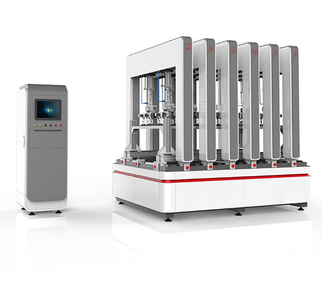
Product Information:
The Mechanical Load Testing Machine is a precision instrument designed to evaluate the mechanical load-bearing capacity of photovoltaic (PV) modules under static and dynamic conditions. It simulates wind, snow, and ice loads through dynamic pressure technology, providing reliable assessment of module structural integrity, compressive strength, and deformation resistance. The machine ensures PV modules perform safely and stably in real-world environmental conditions.
Parameters
| Item | Technical Parameter |
|---|---|
| Machine Dimensions | L 280 × D 180 × H 195 cm |
| Forward Load | 5400 Pa (adjustable) |
| Reverse Load | 2400 Pa (adjustable) |
| Cycle Count | Programmable |
| Dynamic Load Frequency | 7 s ±3 s |
| Dynamic Load | 1000 Pa × 1000 cycles |
| Pressure Control Accuracy | ±5% |
| Force System | Low-friction cylinder + tension/compression sensor (0.1 N accuracy) |
| Frame Material | Aluminum profile structure with electrophoretic surface treatment |
| Max Test Size | 2000 × 1000 mm (customizable) |
| Custom Fixtures | Adjustable according to module installation |
| Electrical Continuity System | DC 150 V / 2 A, real-time monitoring |
| Number of Cylinders | 8 (4 sets × 2) |
| Cylinder Force per Set | >200 kg |
| Cylinder Stroke | 150 mm |
| Suction Cups | 32 (8 sets × 4) |
| Suction Cup Diameter | 120 mm |
| Suction Cup Spacing | ≤200 mm (horizontal/vertical) |
| Suction Cup Joint Rotation | ≥15° |
Features
Low-friction cylinders combined with high-precision force sensors ensure accurate and repeatable loading.
Grouped cylinder and suction cup design allows simulation of varied load combinations and dynamic cycles.
Aluminum profile frame provides uniform force distribution, with corrosion-resistant electrophoretic treatment.
Supports testing PV modules up to 2000×1000 mm; custom sizes available.
Customizable fixtures adapt to different module mounting configurations.
Electrical continuity system monitors module circuitry in real-time.
Mature upper computer software with user-friendly interface, supporting Chinese (simplified/traditional) and English.
Real-time display of pressure, deformation, cycle count, force, and electrical continuity.
Automatic pressure stabilization and continuous data logging.
Test reports can be exported in Word, Excel, PDF, or JPG formats.
Fault warning system provides immediate alerts and operational guidance.
Accessories
Main Machine: Cylinder load system, suction cups, aluminum profile frame.
Upper Computer Software: Real-time control and data acquisition, multilingual interface.
Custom Fixtures: Adjustable for module size and mounting method.
Electrical Continuity Monitoring System: DC 150V / 2A, real-time circuit monitoring.
Force Sensor: Tension/compression sensor with 0.1 N accuracy.
Optional: Pressure calibration kit for periodic calibration of cylinders and sensors.
Test Procedures
Ensure proper grounding and that the electrical continuity system is connected and functional.
Secure the PV module in the custom fixture, ensuring even force distribution.
Set test parameters: forward/reverse load, cycle count, dynamic load frequency.
Confirm cylinder and suction cup operation before starting the test program.
Avoid opening the machine during testing to prevent load interference.
After testing, data is automatically stored; export test reports as needed.
Periodically calibrate cylinder pressure and force sensors to maintain accuracy.
Maintenance Information
Verify grounding and electrical connections before each test.
Inspect custom fixtures and suction cups for wear or damage.
Regularly clean the aluminum frame and maintain electrophoretic surface integrity.
Calibrate cylinders and force sensors periodically to ensure measurement precision.
Ensure the electrical continuity monitoring system functions correctly.
Conclusion
The Mechanical Load Testing Machine provides accurate simulation of static and dynamic mechanical stresses on photovoltaic modules. Its advanced cylinder and force sensor system, customizable fixtures, and real-time monitoring enable reliable evaluation of module structural integrity, deformation resistance, and electrical continuity. This machine is essential for PV module design validation, certification testing, and quality control.
FAQ
What types of loads can the machine simulate?
The machine can simulate forward and reverse static loads as well as dynamic loads that replicate wind, snow, and ice conditions. Dynamic pressure technology ensures realistic stress distribution, allowing evaluation of PV module deformation, compressive strength, and structural reliability.
What are the advantages of the cylinder and force sensor system?
The low-friction cylinder combined with high-precision force sensors guarantees consistent load application and measurement. This system allows accurate simulation of static and dynamic conditions, ensures repeatable results, and provides real-time force and deformation data. The grouped cylinder and suction cup design can emulate various load combinations for more realistic testing scenarios.
How should samples be installed before testing?
Samples must be fixed securely in the custom fixtures, ensuring uniform force distribution. Connect the electrical continuity system to monitor module circuitry. Proper installation prevents slippage or uneven loading during dynamic and static testin
