

Search keywords:
product name, product type, model number,
test method, manufacturer, technique, application
-

Cone Calorimeter
The import of American VTEC, cone calorimeter ultra high cost performance
more
-

Digital Elmendorf Tearing Tester
Pendulum method test material tear strength, operating more simple, more accurate data
more
-

ZwickiLine Materials testing machines
Top of the world's leading universal material testing machine
more
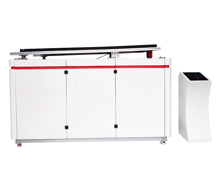
Lead Terminal Strength Tester
BACK
Standards:
IEC 61215-2:2016 – Photovoltaic (PV) Module Design and Certification Standard
Applications:
This tester is widely applied in:
PV Module Lead Terminal Tensile and Torsion Testing: Assess the mechanical strength of lead terminals under controlled force.
Junction Box and Lead Terminal Reliability Evaluation: Verify the adhesion and structural integrity during transport and installation.
R&D Material and Structure Optimization: Validate design improvements in lead terminal materials and mounting structures.
Production Quality Control: Conduct batch inspection and ensure compliance with mechanical strength requirements.
IEC 61215-2 Standard Certification Testing: Confirm lead terminal performance under certified testing protocols.
Installation and Transport Safety Verification: Simulate real-world mechanical stresses to prevent failure.
Product Information:
The Lead Terminal Strength Tester is designed to evaluate the adhesion strength of photovoltaic (PV) module lead terminals to the module body. By applying controlled tensile, torsional, and surface-fixed forces, it simulates mechanical stresses encountered during installation, transportation, and operation. This ensures that lead terminals and junction boxes meet mechanical strength and safety requirements, providing reliable data for quality control, R&D, and certification testing.
Parameters
| Item | Technical Parameter |
|---|---|
| Testable Module Size | 2000 × 1000 mm (customizable) |
| Measurement Accuracy | ≤3% |
| Standard Lead Terminal Fixture | Supports tensile and torsion testing |
| Junction Box Surface Test | Apply 40 N at box center, hold 10 ± 1 s, using weights; timing by stopwatch |
| Tensile Testing | Motorized or weight-based; weights: 30 N, 42 N, 55 N, 70 N, 80 N, 90 N, 100 N, 115 N; cycle: 1 s; repetitions: 54 times (adjustable); displacement manually measured |
| Torsion Testing | Servo motor applied; 220 V 50 Hz, 400 W; continuous current 2.6 A; 17-bit encoder; speed 1–5000; output pulse signal; test time: 1 min (adjustable); torque and angle auto-display |
| Control Method | Touchscreen operation |
Features
Multi-functional Testing: Supports tensile, torsion, and junction box surface-fixed force tests.
High Accuracy: Measurement accuracy ≤3%; torsion angle displayed automatically.
Automated Control: Touchscreen operation, parameter setting, automatic recording of results.
High Flexibility: Customizable module sizes; adjustable weight and test repetitions.
Standards Compliant: Meets IEC 61215-2 requirements, suitable for R&D, certification, and production QC.
Data Visualization: Automatic display of torque, angle, and timing results for evaluation and archiving.
Accessories
Test Table: Accommodates modules up to 2000 × 1000 mm, stable and secure.
Lead Terminal Fixtures: Standard clamps for tensile and torsion testing.
Weights: 30–115 N, adjustable for different tensile tests.
Torsion Servo Motor: 220 V 50 Hz, 400 W, continuous output 2.6 A.
Touchscreen: Parameter setting, operation, and result display.
Other: Timer, sensors, and data acquisition system for automatic display and recording of force, angle, and time.
Test Procedures
Place the PV module on the test table and secure it properly.
Install the appropriate lead terminal or junction box fixture, ensuring a stable grip.
Set tensile or torsion test parameters: weights, repetitions, cycles, torsion time, etc.
Confirm touchscreen parameters and start the test.
Tensile Test: Apply force using motor or weights for the specified cycles; measure displacement manually or automatically.
Torsion Test: Apply torque via servo motor; monitor and record torque and angle in real-time.
After testing, inspect lead terminals and junction box attachment; record results.
Regularly calibrate the servo motor and fixtures to maintain precision.
Maintenance Information
Keep the test table and fixtures clean and free from debris.
Periodically inspect servo motors, lead terminal fixtures, and weights for wear.
Verify touchscreen and data acquisition system functionality.
Perform routine calibration and maintenance to ensure accuracy and safety.
Conclusion
The Lead Terminal Strength Tester provides precise, repeatable evaluation of PV module lead terminal adhesion and junction box reliability. Through controlled tensile, torsion, and surface-applied forces, it simulates real-world mechanical stresses, ensuring compliance with IEC 61215-2. The system supports R&D, production quality control, and certification laboratories, delivering reliable data for module safety and durability assessment.
FAQ
What is the purpose of the Lead Terminal Strength Tester?
It evaluates the adhesion strength of PV module lead terminals and junction boxes under tensile, torsional, and surface-fixed forces. The test simulates stresses during installation, transportation, and operation to ensure mechanical reliability and compliance with IEC 61215-2 standards.
How is tensile testing performed?
Tensile testing is conducted using a motor or weights applied to the lead terminals. Weights ranging from 30 N to 115 N can be used, with cycles of 1 second repeated up to 54 times (adjustable). Displacement is measured manually or automatically. This procedure assesses the adhesion strength of the lead terminals accurately.
How does torsion testing work?
Torsion is applied using a servo motor with 220 V, 50 Hz, and 400 W power. The system allows continuous torque application, real-time monitoring, and automatic display of torque and angle. Test duration is adjustable, typically 1 minute. This ensures lead terminal torsional strength is assessed under controlled conditions.
