




Search keywords:
product name, product type, model number,
test method, manufacturer, technique, application
-
Cone Calorimeter
The import of American VTEC, cone calorimeter ultra high cost performance
more
-
Digital Elmendorf Tearing Tester
Pendulum method test material tear strength, operating more simple, more accurate data
more
-
ZwickiLine Materials testing machines
Top of the world's leading universal material testing machine
more
High and Low Temperature Circular Air Chamber
BACK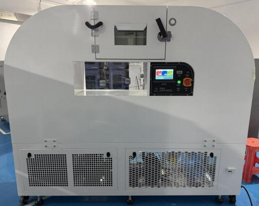


Standards:
Applications:
Product Information:
 This product is specifically designed for combustible gas detectors. It is developed in accordance with GB15322.1-2019 / GB15322.2-2019 / GB15322.3-2019. covering test requirements such as alarm actuation value testing, orientation testing, alarm repeatability testing, high-temperature (operational) testing, low-temperature (operational) testing, and constant damp heat (operational) testing.It is used in conjunction with a self-equipped gas analyzer and gas sampling injection device to conduct the relevant standard tests.Tested products include: household combustible gas detectors, industrial and commercial combustible gas detectors, and industrial and commercial portable combustible gas detectors.
Specification
|
External Dimensions |
W2200 × D400 × H1600 mm |
|
Internal Dimensions |
W2000 × D300 × H300 mm |
|
Temperature Range |
-40°C ~ +70°C, continuously adjustable |
|
Temperature Fluctuation |
±0.5°C (no load, steady state) |
|
Temperature Uniformity |
±2.0°C (no load, steady state) |
|
Temperature Deviation |
±2°C (no load, steady state) |
|
Humidity Range |
Automatically adjusted according to operating temperature; at 40°C, humidity can be precisely controlled up to 96% |
|
Heating Rate |
-40°C ~ +70°C approx. 1–1.5°C/min, non-linear, no load |
|
Cooling Rate |
+70°C ~ -40°C approx. 0.5–1°C/min, non-linear, no load |
|
Gas |
Methane, propane, isobutane, carbon monoxide, and other gases (supplied by customer) |
|
Orientation Test |
45° / 360° rotation; 8 positions |
|
Noise |
Tested according to GB/T14623-2008; noise ≤ 75 dB (measured at 1 m from the equipment door) |
|
Power Supply / Power |
AC 1-phase 220V 50Hz / 6.5 kW |
Chamber Structure
|
1 |
Cabinet Material Composition |
A. Outer wall material: 1.5 mm cold-rolled steel plate with high-grade baking finish coating; B. Inner wall material: 1.0 mm SUS304 stainless steel plate; C. Thermal insulation material: 50 mm rigid polyurethane foam insulation layer (silicon-free). |
|
2 |
Structural Strength |
A. Load-bearing capacity of the chamber bottom plate: ≤100 kg (uniformly distributed load); B. The chamber adopts full welding process, ensuring continuous and dense weld seams, which improves welding strength and airtightness, meeting high reliability requirements. |
|
3 |
Door |
Single-swing hinged door (right handle, left hinge) Mechanical side-mounted latch handle Double silicone sealing gaskets and anti-condensation electric heating device in door frame |
|
4 |
Observation Window |
Multi-layer vacuum glass window with coated heating and anti-frost function installed on chamber door |
|
5 |
Lighting |
LED lighting installed above the observation window, controlled via touch-screen controller |
|
6 |
Test Lead Port |
Built-in (10A) explosion-proof power socket inside chamber (independent wiring for voltage regulation tests), reserved airflow/speed test port |
|
7 |
Casters |
Four sets of high-quality universal wheels with leveling feet |
|
8 |
Electrical Cabinet |
Installed at rear of chamber, equipped with power distribution panel; water-electricity separation design to ensure safety |
|
9 |
Operation Time Counter |
System operating time is continuously accumulated to provide equipment usage records |
|
10 |
Emergency Stop / Start Button |
Manual override control; immediately cuts off main power supply in emergency situations |
Temperature and Humidity Air Circulation System
|
1 |
Composition |
Circulation motor, multi-blade centrifugal fan, heater, refrigeration evaporator, temperature and humidity sensors, etc. |
|
2 |
Control Method |
Forced air circulation with balanced temperature control |
|
3 |
Air Circulation Device |
Long-shaft circulation motor with multi-blade centrifugal fan |
|
4 |
Heating Method |
Steam heating with PID-controlled power output |
|
5 |
Air Cooling Method |
Finned evaporator, capillary tube with proportional refrigeration control |
|
6 |
Air Supply Mode |
Circular horizontal air supply system |
Refrigeration System
|
1 |
Refrigeration Method |
Single-stage mechanical refrigeration cycle |
|
2 |
Refrigeration Section Position |
Located at the lower part of the chamber |
|
3 |
Compressor |
Fully hermetic compressor |
|
4 |
Refrigerant |
Environmentally friendly (ODP = 0) |
|
5 |
Condenser |
Air-cooled finned condenser (also functions as heat exchanger) |
|
6 |
Evaporator |
High-efficiency multi-stage aluminum fin evaporator (thickened fins), also functions as dehumidifier |
|
7 |
Dry Filter |
|
|
8 |
Throttling Device |
Capillary tube + proportional control |
|
9 |
Dehumidification |
Refrigeration-based dehumidification; air passes through evaporator below dew point temperature, moisture is condensed and removed |
|
10 |
Control Method |
A. System automatically controls compressor operation and cooling capacity according to test conditions to ensure optimal working status and extend service life; B. Designed with hot gas bypass energy-saving function and suction cooling bypass to protect compressor safety |
|
11 |
Refrigeration Process |
A. Compressor protection functions including automatic suction and discharge pressure protection to maintain normal operating temperature and extend service life; B. Refrigeration piping uses high-quality oxygen-free copper tubes with nitrogen-protected welding to prevent oxidation inside tubes; C. Suction and discharge pressures are monitored via sensors connected to control system, and discharge pressure is directly displayed via Danfoss pressure gauge; D. Stainless steel drip tray is installed under compressor to collect condensate and discharge it centrally from the rear bottom of the chamber |
|
12 |
Vibration & Noise Reduction |
Vibration: compressor mounted on damping springs or rubber pads to reduce vibration transmission to base frame; Noise reduction: sound barrier panels installed at air inlet and outlet to reduce noise transmission; low-speed high-airflow condenser fans are used to achieve low-noise operation |
 Heating and Humidification System
|
1 |
Heater |
Finned heating element (surface temperature of heating tube controlled below 100°C) |
|
2 |
Control Method (Heating) |
Controller reads analog signal from temperature sensor and outputs control signal via SSR solid-state relay, achieving high-precision non-contact switching control |
|
3 |
Humidifier |
Stainless steel armored humidifier (surface evaporation type); equipped with water shortage protection to prevent dry burning; low output load, large heat exchange area, long service life, and fast humidification |
|
4 |
Control Method (Humidification) |
Controller reads analog signal from temperature sensor and outputs control signal via SSR solid-state relay for high-precision non-contact switching control |
|
5 |
Sensor |
Platinum resistance temperature and humidity sensor with high accuracy |
|
6 |
Anemometer |
Handheld anemometer |
Control system
|
1 |
Controller |
Equipped with a mainstream programmable logic controller; 7-inch full-color touchscreen human-machine interface (HMI) with bilingual Chinese/English display; menu-based operation for easy user control |
|
2 |
HMI Functions |
A. Real-time monitoring of controller data, signal status, and output status; B. During testing, real-time display of set temperature/humidity, measured temperature/humidity, heating and humidification output, running time, operation parameters, and PID parameters |
|
3 |
Control Method |
A. PID + SSR control mode with zone PID adjustment and automatic tuning function; B. At high temperature, PID automatically adjusts heating output; in humidity mode, PID automatically adjusts heating and humidification output; C. Compressor start/stop is automatically recognized by the controller without manual setting |
|
4 |
Display Accuracy |
Temperature: 0.1°C; Humidity: 0.1% RH; Time: 1 min |
|
5 |
Operation Modes |
Constant value operation, program operation |
|
6 |
Program Capacity |
120 groups of programs, 100 segments per program, 99.999 cycles; each segment up to 99.999 hours 59 minutes; freely configurable segmentation with multiple PID control groups |
|
7 |
Communication Interface |
USB interface for program upload/download, internal parameter import/export, and historical data export |
|
8 |
USB Storage |
Supports USB flash drive for downloading historical curves and data; hot-swappable function supported |
|
9 |
Password Protection |
Controller equipped with password protection function |
|
10 |
Power Failure Protection |
Supports power-off recovery with selectable modes: Stop / Cold start / Hot start |
|
11 |
Power-on Scheduling |
Programmable start time; system automatically starts operation after preset time once powered on |
|
12 |
Electrical Components |
Main electrical control components are high-quality branded parts; detailed list available in main material specification sheet |
Safety Protection Device
|
1 |
Refrigeration System |
A. Compressor overpressure protection; |
|
2 |
Heating & Humidification System |
A. Single-phase switch overload protection; |
|
3 |
Power Supply |
Molded case circuit breaker protection. 220V high-voltage system with explosion-proof plug; separation of strong and weak current; independent signal wiring. |
Operating Conditions
|
1 |
Installation Site –Transport Passage |
A. The chamber must be able to pass through according to its overall external dimensions; B. Special attention shall be paid to turning corners, doorway size, elevator size, and other restricted passages |
|
Floor Load Capacity |
Floor load-bearing requirement: ≥600 kg/m² (applicable to installations on upper floors or elevated platforms) |
|
|
Installation Space Requirements |
|
|
|
2 |
Operating Environment Conditions |
Ambient temperature: 5°C ~ 35°C; Relative humidity: ≤85% RH; Atmospheric pressure: 86 kPa ~ 106 kPa |
|
3 |
Power Supply Conditions |
Frequency allowable fluctuation: (50 ± 0.5) Hz; Protective grounding resistance: < 4 Ω; A dedicated air switch or power switch with appropriate capacity must be provided at the installation site, and it must be used exclusively for this equipment |
|
4 |
Storage Conditions |
B. If storage temperature is below 0°C, for water-cooled and humidity-type chambers, all residual water inside the system must be drained to prevent freezing and pipeline damage |
Accessories
Packing List: 1 copy
Operation Manual: 1 copy
Controller Manual: 1 copy
Test Report: 1 copy
