


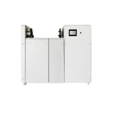
Photovoltaic module wire tube bending testing machine IEC61730-2:2004
2026/01/04
Share:
Core Mission
The core purpose of bending tests on photovoltaic module conduits (usually referring to the output cables and their protective sheaths leading out of the junction box) is to simulate the bending stress that the leads may repeatedly experience during installation, transportation, and long-term operation of the module. International Electrotechnical Commission (IEC) standards, particularly **IEC 61215 (Design Qualification and Type Approval of Ground-Mounted Crystalline Silicon Photovoltaic Modules)** and **IEC 61730 (Safety Qualification of Photovoltaic Modules)** series, clearly specify requirements for this type of mechanical stress testing. For example, the "Lead End Bending Test" in sequence M13 of IEC 61215-2:2021 is a direct operational guideline for this testing machine.
The fundamental task of the testing machine is to rapidly simulate the repeated bending of cable joints caused by vibration and wind in outdoor environments over many years through quantifiable and repeatable mechanical motion. This allows for the exposure of potential design defects or manufacturing problems in a short time under laboratory conditions, such as:
Broken copper wires inside the conductor
Loose solder joints or contacts inside the junction box
Cracks in the cable insulation or sheath under stress
Failure of the seal leading to moisture intrusion
Technical Principles and Core Components
A typical photovoltaic module cable bending tester is an integration of mechanical design, motion control, and measurement sensing technology. Its working principle is not simply bending, but a highly standardized scientific process.
1. Mechanical Actuation System:
This is the main body of the tester. Typically, it includes a robust test platform for securing the junction box portion of the photovoltaic module. The core actuator is one or more robotic arms or shafts that precisely clamp the cable at a certain distance from the junction box outlet (e.g., 400mm as specified in standards). The machine drives this clamping point to reciprocate the cable at a specified angle within a vertical or horizontal plane with a fixed radius of rotation (e.g., R=125mm±5mm). Test standards typically require more than **1000** cycles to verify its long-term durability.
2. Load Simulation Unit:
To realistically simulate the tension experienced by the cable, a standardized weight load (e.g., 20N, 40N, or 60N force depending on the cable specification) is applied to the end of the cable during testing. This constant tension ensures that each bend is subjected to stress consistent with actual working conditions, making the test results more relevant and valuable for real-world applications.
3. Intelligent Control System:
Modern testing machines are generally controlled by a Programmable Logic Controller (PLC) and a Human-Machine Interface (HMI). Operators can easily set key parameters:
Bending Angle** (e.g., ±90°, ±180°)
Bending Speed** (e.g., 1 bend/second)
Total Cycles** (e.g., 1000 cycles, 2000 cycles)
Test Mode** (unidirectional, bidirectional, specific angle hold)
The system automatically counts and stops when the set number of cycles is reached or a fault occurs (e.g., an open circuit is detected through continuous monitoring).
4. Online Monitoring and Diagnostic System (Advanced Functions):
More advanced equipment integrates real-time monitoring functions:
Electrical Continuity Monitoring: During testing, a small detection current is continuously supplied to the cable under test. If an internal fracture causes a sharp increase in resistance or an open circuit, the system immediately alarms and records the number of failed cycles. This is the core basis for determining whether the test passes.
Torque/Force Monitoring: Monitors changes in resistance torque during bending, indirectly reflecting trends in cable hardening or internal structural changes.
Visual Assistance System: A high-definition camera records changes in the physical state of the bending area, aiding subsequent failure analysis.
Test Procedure and Result Judgment
A complete test follows a rigorous process:
1. Sample Preparation: Securely fix the junction box of the photovoltaic module under test onto the testing machine fixture, arranging the cable according to the specified length and path.
2. Parameter Setting: Set the bending radius, angle, speed, load, and number of cycles according to testing standards (such as IEC, UL 1703. etc.) or company internal specifications.
3. Load Application: Suspend a standard weight at the end of the cable.
4. Test Execution: Start the machine and begin automatic cyclic bending. The continuous monitoring system operates continuously during this process.
5. Post-Test Inspection:
Primary Judgment: Check for electrical continuity failure (open circuit) during the test. If it occurs within the specified number of cycles, the test fails.
Secondary and auxiliary assessments: After completing the prescribed cycle, a series of checks are performed: visually inspect the cable insulation for cracks or damage; check the junction box seal for integrity; conduct insulation resistance testing (required to be ≥ standard initial value); conduct wet leakage current testing (to verify sealing), etc.
Only when all requirements are met can the component's cable connection system be considered to have passed this stringent mechanical durability test.
Industry Application Value
Photovoltaic Power Plant Construction
1. In centralized photovoltaic power plants, conduits must withstand multiple stresses, including support vibration and temperature changes. A 500MW photovoltaic power plant used a testing instrument to conduct batch testing on purchased conduits. It was found that a certain batch of products exhibited conductor breakage after only 2000 bends in simulated operating conditions. By tracing the production process, it was discovered that the copper conductor purity did not meet the 99.99% standard, successfully avoiding potential safety hazards.
2. New Energy Vehicle Charging Facilities
Charging pile cable conduits must meet the 10.000-cycle bending test standard of GB/T 33594-2017. A testing institution used a testing instrument with a cryogenic chamber to verify the low-temperature flexibility of the cable sheath material at -35℃. The test showed:
Traditional TPE materials cracked after 8000 cycles.
New TPU materials remained intact after completing 10.000 cycles.
This data directly drove the industry's material upgrade; currently, TPU materials have increased their market share in the charging pile cable market to 65%.
3. Rail Transit Systems
CRCC certification requires that communication cables, after undergoing 30.000 bends, exhibit an attenuation increase of no more than 0.2 dB/m. A subway project used a testing instrument to conduct accelerated life tests on signal cables and discovered that a batch of products, due to insufficient shielding braid density, exhibited excessive signal attenuation after only 25.000 bends. By optimizing the production process, the company's products passed CRCC certification on the first attempt, saving over 2 million yuan annually in rework costs.
Technological Development Trends
With the development of photovoltaic technology, testing equipment is also constantly evolving:
1. Multi-station and Automation: To improve testing efficiency, dual-station or even four-station automated testing machines are becoming the trend, enabling automatic loading and unloading, continuous testing, and meeting the needs of large-scale production.
2. Environmental Composite Testing: Simple mechanical bending can no longer meet higher reliability requirements. Combining bending tests with high and low temperature humidity chambers allows for comprehensive stress testing based on **temperature-humidity-bending**, more realistically simulating the effects of diurnal temperature variations and humid climates on material properties (such as sealant elasticity and plastic brittleness), enabling more stringent defect screening.
3. Data-driven and intelligent: Test data is no longer simply "pass/fail". Equipment integrates a data management system, recording complete parameters and process curves (such as drag torque change curves) for each test. Big data analysis can predict the lifespan distribution of different designs, providing in-depth insights for reliability engineering.
4. Adaptable to new modules: For modules with increasing power and thicker cables, the testing machine needs to provide greater load capacity; for special structures such as bifacial and flexible modules, corresponding customized fixing and testing solutions are also required.
While the photovoltaic module conduit bending tester does not directly participate in power generation, it silently safeguards the safety baseline and long-term benefits of photovoltaic systems as a "rigorous examiner." Through scientific and precise physical simulation, it reveals potential connection failure risks that may occur decades later in the laboratory. In today's photovoltaic industry, which is moving towards "quality and efficiency improvement" and pursuing lower levelized cost of electricity (LCOE), its value is becoming increasingly prominent. It is not only a benchmark for quality control, but also an innovative catalyst driving the continuous iteration of junction boxes, cables, and connection technologies towards higher reliability, providing a solid technical guarantee for ensuring that every photovoltaic module can safely and stably fulfill its decades-long power generation mission.
Previous: What is a water repellency tester?
N e x t : What is Flexible carpet thickness tester?
