


What is the reverse bend test of wire?
2026/01/26
Share:
Definition and Purpose of the Test
The wire reverse bend test involves fixing one end of the specimen and repeatedly bending it 90° to the left and 90° to the right over a predefined support structure, using a standardized cylindrical support to ensure a controlled bending radius. The purpose of the test is to determine how many reverse bending cycles the wire can withstand after elastic deformation before the occurrence of cracks, fracture, or unacceptable residual plastic deformation.
Unlike simple bending or unidirectional bending tests, the core feature of the reverse bend test lies in the cumulative damage behavior of the material under continuous loading in alternating directions. This stress mode more closely represents real service conditions, such as repeated bending and positional adjustments encountered during machining, installation, assembly, and long-term operation. Through reverse bend testing, engineers can evaluate key properties including toughness, fatigue performance, plastic ductility, and coating resistance.
Test Principle
The fundamental principle of the reverse bend test is to apply alternating bending loads that force the wire to undergo asymmetric cyclic plastic deformation, thereby revealing performance degradation under repeated loading. The specimen is typically clamped at one end, while the other end is repeatedly bent around a cylindrical support by a mechanical arm or bending arm. Each bending operation usually reaches 90°, followed by bending in the opposite direction in an alternating sequence.
This process produces several mechanical behavior stages:
Elastic deformation stage: During initial bending, the wire deforms elastically and returns to its original shape after load removal.
Plastic deformation stage: As strain increases, the material exceeds its elastic limit and irreversible plastic deformation occurs.
Fatigue damage accumulation: Under cyclic stress, microcracks gradually develop within the material structure.
Failure stage: When accumulated plastic deformation reaches a critical level, visible failure occurs, such as crack propagation or fracture.
Typical evaluation indicators include the number of reverse bending cycles, crack initiation and propagation behavior, fracture morphology, and residual plastic deformation. These indicators describe material performance limits and failure modes, providing a scientific basis for design and quality assessment.
Reverse Bend Testing in the International Standard System
Reverse bend testing is a standardized mechanical test method governed by international standards. One of the most representative standards is the ISO 7801 series, which is used to evaluate the plastic deformation resistance of metal wires under reverse bending loads.
ISO 7801 Standard
According to the latest ISO 7801:2024 standard, the test method specifies the basic principles, test conditions, support radius, specimen size range, and equipment requirements for reverse bend testing. The standard applies to metallic wires with diameters or characteristic dimensions typically ranging from 0.3 mm to 10 mm, or as defined by relevant product standards.
The standard clearly defines:
Specimen size ranges: Standardized requirements for different wire diameters
Bending angle and direction: Repeated left and right bending at 90° over a cylindrical support
Equipment requirements: The machine must ensure consistent, reliable, and repeatable bending actions
Data recording and evaluation criteria: Recording of reverse bending cycles and failure characteristics for performance assessment
Standardization ensures that test results obtained in different countries and institutions are comparable, which is essential for international certification, technical cooperation, and scientific research.
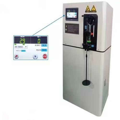
Equipment Configuration Requirements
Reverse bend testing equipment is typically referred to as a Reverse Bend Testing Machine, and its main components include:
Clamping unit: For fixing one end of the specimen
Bending arm or drive mechanism: Precisely controls bending angle and direction
Support assembly: Provides a fixed cylindrical support radius
Control system: Sets bending cycles, speed, and motion sequence
Data recording system: Includes counters, angle sensors, or digital displays
Modern systems are commonly equipped with electric or servo drive systems, central control interfaces, and safety protection devices, significantly improving automation and precision. They are capable of performing reverse bending cycle tests ranging from dozens to tens of thousands of cycles, with precisely controlled frequency and bending angles.
A key requirement of the equipment is the consistency and repeatability of bending motion, ensuring that test results are not affected by mechanical deviations. Standardized support radii and clamping methods further guarantee consistency and comparability between different test batches.
Operating Procedure
The typical operating process of a reverse bend test includes the following steps:
Sample Preparation
Cut the wire specimen to the length specified by the standard, remove surface contaminants or defects, and ensure that the diameter falls within the applicable standard range.
Clamping Installation
Fix one end of the specimen in the machine clamp, ensuring firm fixation and proper alignment of the specimen axis relative to the support axis.
Support and Parameter Setting
Adjust the cylindrical support radius according to the test requirements or standard specifications, and set the bending angle (usually ±90°) and the number of cycles.
Test Cycle Execution
Start the testing machine so that the bending arm performs alternating bending actions according to the preset program. The equipment automatically controls angles and counts cycles.
Data Recording and Termination Criteria
During the test, record the number of reverse bending cycles and observe changes in specimen condition. After completion, evaluate whether performance criteria are met, such as absence of cracks, fracture, or excessive residual plastic deformation.
Evaluation Criteria
Common evaluation indicators in reverse bend testing include:
Maximum cycle count: Number of bending cycles sustained under specified conditions
Crack initiation cycle: Cycle number at which the first crack appears
Residual plastic deformation: Degree of permanent deformation after unloading
Failure mode analysis: Fracture morphology and surface condition changes
These indicators collectively reflect material ductility, toughness, and fatigue resistance, and provide essential data for studying microstructural characteristics, heat treatment processes, and manufacturing quality.
Practical Application Value
Material Research and Selection
In new material development, reverse bend testing reveals fatigue behavior and service life under repeated deformation loads, supporting material optimization and process improvement.
Quality Control and Product Certification
Routine reverse bend testing of production-line wire products ensures performance stability and batch consistency, meeting regulatory and market requirements.
Reliability Evaluation and Engineering Safety
For applications such as spring steel wire, cables, and metal ropes, reverse bending performance is a critical reliability indicator. This test helps determine susceptibility to fatigue failure under long-term service conditions.
As a standardized mechanical testing method, the wire reverse bend test provides a comprehensive evaluation of plastic deformation capacity, fatigue performance, and durability through the application of alternating bending cycle loads. Supported by the ISO standard system, this method standardizes operating procedures and testing principles, providing a scientific foundation for material performance evaluation, product quality assurance, and engineering reliability analysis. With the continuous advancement of materials engineering and industrial quality standards, reverse bend testing will continue to play an irreplaceable role in research, manufacturing, and certification fields.
Previous: Wire Torsion and Winding Tester,ISO 9649:1990
N e x t : Metal Wire Wrap Tester,ISO 4101
