


Blow-By Test Rig,ISO 8178
2026/02/26
Share:
What is Blow‑By and Its Causes
Blow‑by refers to the portion of high-pressure combustion gases that escape past the piston rings into the crankcase during engine operation and are expelled through the crankcase ventilation system. This gas mixture typically contains combustion gases, air, water vapor, fuel vapor, and oil mist. The primary causes of blow‑by include imperfect piston ring-to-cylinder wall sealing, worn piston installation clearances, ring sticking, and uneven thermal expansion.
Blow‑by reflects engine sealing performance and varies depending on wear, engine operating conditions, and design structure. All four-stroke engines exhibit a certain level of blow‑by under normal conditions because piston rings cannot completely seal the interface between the combustion chamber and the crankcase.
While blow‑by is a design-allowed phenomenon, excessive blow‑by may indicate significant seal wear or piston ring degradation, leading to power loss, increased fuel consumption, oil contamination, and accelerated mechanical wear. Accurate measurement of blow‑by is therefore a critical aspect of engine testing and development.
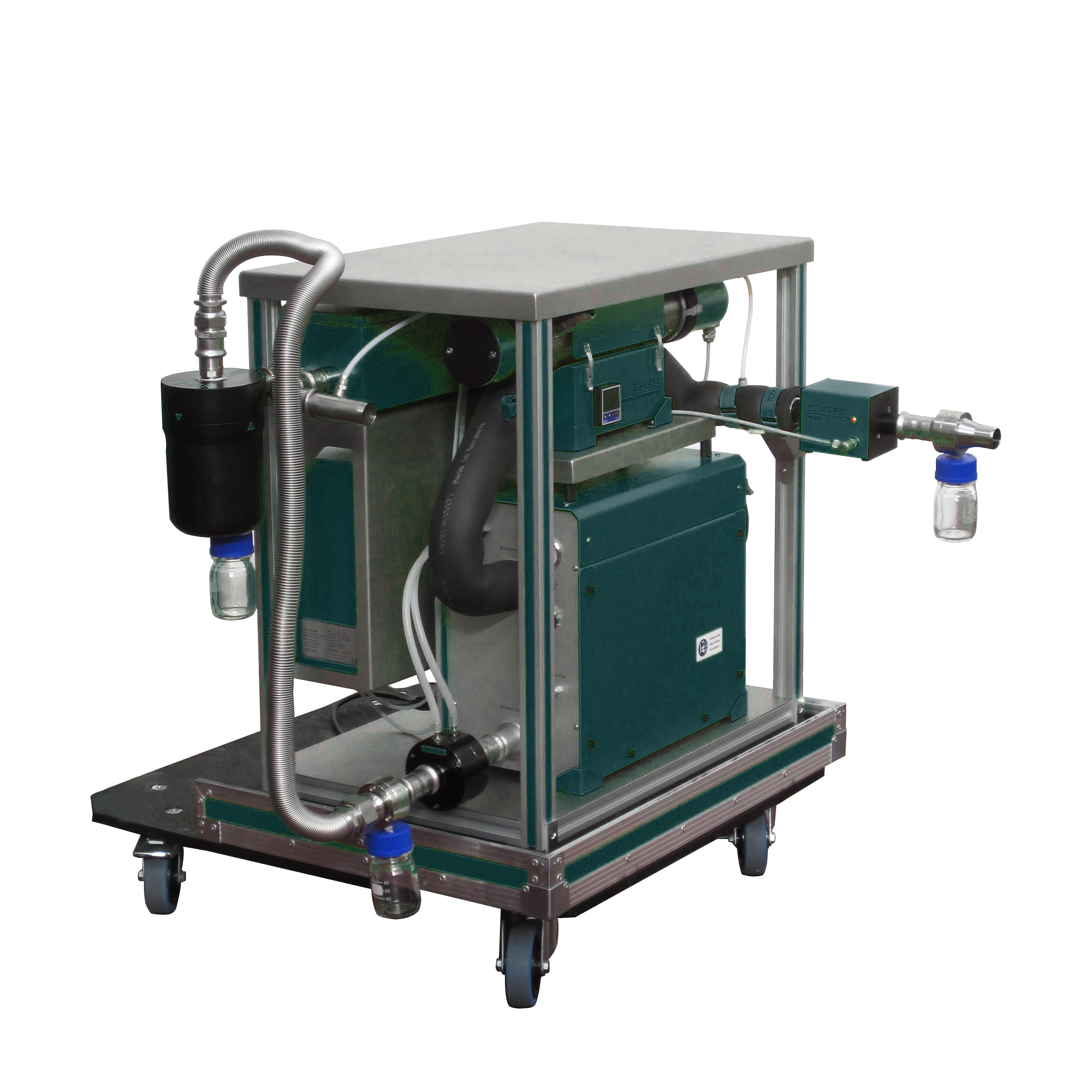
Technical Principles and Measurement Objectives of Blow‑By Test Rigs
The primary task of a blow‑by test rig is to quantify the flow and physical characteristics of gases (including oil mist and combustion gases) escaping from the crankcase during engine operation. Essentially, the test rig is an integrated measurement system that can be connected to the engine’s crankcase ventilation outlet in a laboratory or test bench, directing the blow‑by gases into measurement devices.
A typical blow‑by test system consists of:
Gas sampling unit: Captures all or part of the crankcase gas stream.
Flow measurement system: Measures the blow‑by gas flow rate, usually expressed as volumetric flow (L/min) or mass flow.
Oil mist and particle concentration measurement unit: Detects oil droplets or mist in the blow‑by gas using optical or gravimetric methods.
Automated control and data acquisition system: Records parameters such as pressure, temperature, and flow in real time and synchronizes with engine signals to map engine states to blow‑by behavior accurately.
While traditional blow‑by measurement methods rely on mechanical devices to measure pressure differences or crankcase pressure, specialized blow‑by test rigs achieve higher precision, wider dynamic range, and online measurement under varying engine conditions such as idling, acceleration, and deceleration.
Testing Methods and Equipment Workflow
A complete blow‑by testing process generally involves the following steps:
1. Equipment connection and preparation
The test rig is installed on an engine test bench and connected to the crankcase ventilation system. Sampling lines are sometimes required to direct gases safely to the test equipment, preventing damage or measurement errors from oil mist and high temperatures. Heating control is often employed to avoid condensation of oil mist in cold conditions, ensuring data accuracy and repeatability.
2. Online continuous sampling and measurement
During operation under different loads and speeds, the rig continuously samples crankcase gases. Flow, temperature, and pressure parameters are recorded. Oil mist measurement modules assess oil droplet concentration using optical or particulate techniques, providing data such as oil content (g/m³) and mass flow (g/h), which are critical for evaluating oil carryover and consumption.
3. Data acquisition and engine state synchronization
Modern rigs feature digital data acquisition interfaces that synchronize blow‑by measurements with engine speed, torque, fuel consumption, and emissions. By mapping blow‑by data to the engine map, engineers can analyze blow‑by behavior under different operating conditions, aiding engine development, seal design validation, and lifespan evaluation.
Practical Applications of Blow‑By Test Technology
1. Engine development and calibration
During engine R&D, engineers assess how different designs—piston ring geometry, surface treatment, or cylinder block structure—affect blow‑by. Precise measurement enables optimization of design parameters, improving sealing performance, reducing fuel consumption, and mitigating wear.
2. Oil carryover and filtration system assessment
Blow‑by gases carry fine oil droplets, which can affect crankcase ventilation and oil separation systems. Blow‑by rig measurements allow evaluation of oil separator efficiency and filtration design optimization by quantifying oil droplet concentration and mass flow.
3. Engine wear diagnosis and lifespan monitoring
Excessive blow‑by indicates worn seals or abnormal operation. Continuous measurement serves predictive maintenance, providing early warning of potential issues, especially for heavy-duty engines or diesel generators requiring stable long-term operation.
Comparison with Traditional Testing Methods
Conventional blow‑by measurement often relies on pressure gauges, velocity meters, or mechanical meters, such as water column differential devices, providing only approximate data. These methods cannot capture oil mist content or real-time dynamic variations with engine load.
In contrast, blow‑by test rigs use electronic sensors and automated data acquisition systems, offering:
Wider flow measurement range (from a few liters per minute to thousands of liters per minute).
Quantitative oil mist measurement, not just gas flow.
Comprehensive datasets synchronized with engine control parameters for modeling and analysis.
High automation, reducing human error.
Data Analysis and Engineering Value
Blow‑by test results enable analysis of several key aspects:
Blow‑by flow curves: Show variation in blow‑by flow under idle, partial, and full load conditions, allowing comparison across designs.
Oil concentration and carryover: Quantifies lubrication oil loss, reflecting seal effectiveness and impacts on ventilation and filtration systems.
Correlation with engine states: Software tools correlate blow‑by data with engine speed and fuel consumption to identify abnormal operating conditions or lubrication imbalances.
Technical Challenges and Future Directions
Despite current capabilities, challenges remain:
Complex multi-component gas mixtures: Accurately distinguishing and quantifying gases, oil mist, and water vapor is technically challenging.
Dynamic testing precision: High-speed and high-load transient conditions require synchronized high-frequency sampling.
Integration with engine control systems: Future rigs may integrate more deeply with ECU platforms to actively optimize sealing performance and fuel consumption.
Computational fluid dynamics (CFD) simulations are increasingly used to complement experimental data and understand blow‑by flow mechanisms for improved engine design.
Blow‑by test rigs are indispensable precision instruments in modern engine development and performance evaluation. By quantitatively measuring crankcase gas flow and oil droplet concentration, they provide a scientific basis for engine seal design, lubrication system optimization, filter efficiency assessment, and lifespan management. Compared with conventional measurement tools, blow‑by test rigs offer high precision, automation, and multi-parameter integration, delivering significant value in engineering practice.
Understanding blow‑by testing not only clarifies the nature of internal engine leaks but also assists engineers in developing more efficient, reliable, and optimized powertrains. With ongoing technological advancements, test rigs will continue to improve in real-time measurement, dynamic analysis, and intelligent control capabilities.
Previous: What are the requirements for HEPA filter testing?
N e x t : How to perform an air velocity test?
