


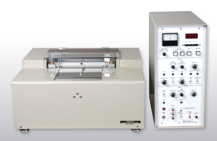
What is a Tensile and Shear Tester?
2026/06/01
Share:
Main Testing Modes and Applications of a Tensile and Shear Tester
To better understand the characteristics of this equipment, we can explain it from the following main testing modes and their applications.
1. Tensile Testing Mode
Tensile testing is one of the most fundamental methods for evaluating material properties. In this mode, the upper and lower grips of the machine clamp both ends of the specimen and gradually apply a tensile force at a constant or controlled rate until the sample eventually breaks. Throughout the process, both the applied force and the specimen’s elongation are precisely recorded.
Through tensile testing, a series of key material properties can be obtained. These include strength, which refers to the maximum tensile load a material can withstand before failure; elastic modulus, which reflects a material’s resistance to elastic deformation—commonly understood as its stiffness; and ductility, which describes the extent to which a material can deform before fracture. Brittle materials such as glass exhibit very low ductility and fracture easily with minimal deformation, while ductile materials such as low-carbon steel can undergo significant elongation before breaking.
Compared with simple devices that only indicate whether a material has broken or not, electronically controlled high-quality testing machines provide a complete force–displacement curve. This curve acts like a “fingerprint” of the material, containing full information from initial loading to final fracture, enabling much deeper and more comprehensive analysis.
2. Shear Testing Mode
Shear testing is used to determine a material’s ability to resist shear stress. Shear deformation occurs when forces cause adjacent layers within a material to slide relative to each other. In this test, the specimen is placed in a specialized shear fixture, and the machine applies force that drives relative motion between parts of the fixture, thereby generating shear stress on the sample.
Shear properties are critical for applications such as rivets, pins, adhesives, and interlaminar bonding strength in composite materials. For example, evaluating the bonding strength of an adhesive requires shear testing to determine the interface’s resistance to failure under sliding forces.
Shear testing places high demands on alignment accuracy and fixture design. Conventional loading systems often struggle to achieve a pure shear state and may introduce unwanted bending or tensile stress components. High-quality electronic testing machines, through precision mechanical structures and dedicated shear fixtures, can better ensure accurate application of shear force and produce more reliable shear strength data.
Application Industries of a Tensile and Shear Tester
A tensile and shear tester is mainly used to evaluate the mechanical properties of materials under combined tensile and shear loads. Its core application areas include the following:
1. Adhesives and Sealant Industry
It is widely used to evaluate the tensile-shear strength of bonded joints. This is essential in the development and quality inspection of adhesives used in aerospace, automotive manufacturing, and electronic packaging applications.
2. Metals and Composite Materials R&D
The equipment is used to test the interface bonding strength of metal lap joints and fiber-reinforced composites (such as carbon fiber/epoxy systems). It plays a key role in the manufacturing of aerospace structural components, wind turbine blades, and rail transit parts.
3. Electronic Packaging and PCBA Manufacturing
It is applied to test the shear and pull strength of chip solder joints, wire bonding, and BGA solder balls. This ensures the reliability and durability of microelectronic components.
4. Construction Materials and Coating Systems
It is used to evaluate the shear bonding performance of concrete adhesives, tile adhesives, and anti-corrosion coatings on substrates, ensuring compliance with construction industry standards.
5. Research Institutions and Quality Inspection Agencies
Universities, research institutes, and third-party testing laboratories use this equipment for material interface mechanism studies, compliance verification with standards, and failure analysis.
Technical Features of the Tensile and Shear Tester
The tensile and shear tester demonstrates significant advantages, mainly reflected in the following aspects:
First, the device optimizes the tightening mechanism between the motor-driven system and the grips, effectively eliminating sample slack before testing. This design minimizes errors caused by improper operator handling, thereby significantly improving the accuracy and reliability of data acquisition.
Second, the tester is equipped with a display resolution of 0.01. allowing highly precise numerical representation of subtle differences in material behavior during micro-scale tensile and shear processes. This high-resolution capability provides users with more detailed and accurate data for analysis.
Basic Principle of Tensile-Shear Strength Testing
Tensile-shear strength testing primarily simulates the combined tensile and shear loading conditions that materials may experience in real-world applications. During the test, specimens are typically fixed in an overlapped (lap joint) configuration. An axial tensile load is applied using a universal testing machine, causing shear stress to develop in the overlapping region. As the load increases, failure occurs along the shear plane, and the maximum load value is recorded. The tensile-shear strength is then calculated by dividing the maximum load by the overlap area. The unit is usually expressed in megapascals (MPa).
Testing Equipment and Specimen Preparation
Tensile-shear strength testing requires specialized mechanical testing equipment and supporting tools. The main equipment includes a high-quality universal testing machine, dedicated shear fixtures, and a data acquisition system. The testing machine must have sufficient load capacity and high precision, and be capable of maintaining a constant loading rate. The fixtures must ensure proper alignment of the specimen during testing to avoid additional bending or torsional stresses.
Specimen preparation is a critical factor that significantly influences test results. Specimens are typically machined into specific shapes and dimensions according to relevant standards. For example, metal tensile-shear specimens are often prepared as rectangular lap joints, while adhesive specimens consist of overlapped metal or composite sheets. During preparation, the bonding surfaces must be flat and clean. For adhesive samples, the adhesive layer thickness and curing conditions must be strictly controlled. For welded joints, specimens should be extracted from actual welded components while preserving the original weld structure.
After preparation, all specimens should undergo visual inspection to eliminate those with defects such as bubbles, cracks, or misalignment. If necessary, dimensional measurements should be performed to accurately determine the overlap area.
Test Procedure and Operational Key Points of a Tensile-Shear Tester
The tensile-shear strength testing process includes equipment preparation, specimen installation, test execution, and data recording.
Detailed Procedure
1. Machine Calibration
Before testing, the testing machine should be calibrated for force measurement and speed verification to ensure it is operating under normal conditions. The gripping surfaces of the fixtures should be checked to ensure they are flat and free from wear.
2. Specimen Installation
Place the specimen correctly into the fixtures, ensuring that the center of the lap joint is aligned with the axis of the grips. When tightening the fixtures, apply force evenly to avoid premature damage from over-tightening or slippage caused by insufficient clamping force.
3. Parameter Setting
Set the loading rate according to relevant standards, typically in millimeters per minute. Configure the data acquisition frequency to ensure a complete recording of the load–displacement curve.
4. Test Execution
Start the testing machine and apply tensile load. Observe the deformation and failure process until the specimen completely separates. Record the maximum load value and failure mode.
5. Data Recording
Save all load and displacement data during the test, and take photographs of the failed specimens. Document the fracture location and surface morphology.
During operation, environmental stability must be maintained to avoid variations in temperature and humidity that may affect results. For high- or low-temperature testing, an environmental chamber should be used. Each sample group should include a sufficient number of specimens—typically no fewer than five—to ensure statistical reliability.
Result Calculation and Data Analysis
After obtaining test data, calculations and analysis are required to evaluate material performance. Based on the recorded failure load and specimen overlap area, the tensile-shear strength of each specimen is calculated. The average strength, standard deviation, and coefficient of variation are then determined to assess data dispersion.
Failure mode analysis is a critical part of result interpretation. Common failure modes include:
Cohesive Failure: Occurs within the material itself, indicating that the interface bonding strength exceeds the material strength.
Adhesive (Interfacial) Failure: Occurs at the bonding or welding interface, indicating insufficient interface strength.
Mixed Failure: A combination of cohesive and interfacial failure characteristics.
By analyzing failure modes, the causes of insufficient strength can be identified, providing guidance for material improvement or process optimization.
A standard test report typically includes specimen information, testing conditions, strength values, failure modes, and additional remarks. The results can be compared with standard requirements or historical data to evaluate whether the material is qualified or to analyze performance trends over time.
Factors Affecting the Results of a Tensile-Shear Testing Machine
The results of tensile-shear strength testing are influenced by multiple factors. Understanding these factors helps improve testing accuracy and repeatability.
1. Specimen Preparation Factors
The surface roughness and cleanliness of the lap joint, adhesive layer thickness, and weld geometry all directly affect the measured strength. The specimen preparation process must strictly follow relevant standard procedures to ensure consistency and reliability.
2. Testing Conditions
Changes in loading rate may cause materials to exhibit different mechanical responses. A higher loading rate may lead to higher measured strength values, while a lower rate may result in reduced strength readings. Environmental temperature also affects material behavior, particularly for polymer-based materials.
3. Equipment and Operational Factors
Testing machine accuracy, fixture alignment, and clamping force all contribute to measurement deviations. In addition, the operator’s experience and skill level can introduce variability in the results.
4. Material Properties
Intrinsic factors such as material anisotropy, internal defects, and aging conditions can lead to natural dispersion in strength values.
During testing, these variables should be systematically controlled, and key testing conditions should be clearly documented in the report to ensure result reproducibility and comparability.
Applications and Significance of the Tensile-Shear Testing Machine
Tensile-shear strength testing has wide-ranging industrial applications and significant engineering value. In the aerospace industry, it is used to evaluate the reliability of composite joints and bonded structures. In automotive manufacturing, it serves to verify weld strength and adhesive performance. In the electronics industry, it is applied to assess the mechanical integrity of wire bonding and packaging materials.
Through this type of testing, the shear load-bearing capacity of materials can be quantified, providing essential input parameters for structural design. The results are also valuable for process comparison, such as optimizing adhesive curing conditions or welding parameters. Regular tensile-shear strength testing helps monitor product quality consistency and detect deviations in the production process in a timely manner.
In the development of new materials or joining technologies, tensile-shear strength data serves as a key performance indicator, guiding formulation adjustments and structural improvements. The accumulation of test data also contributes to the establishment of material databases, supporting service life prediction and failure analysis.
In summary, as a fundamental mechanical testing method, the proper execution and accurate interpretation of tensile-shear testing are crucial for material evaluation. Through standardized procedures and rigorous data analysis, reliable strength parameters can be obtained to support product quality improvement and technological advancement. As material applications continue to expand and performance requirements increase, tensile-shear testing technology will continue to evolve, providing more effective support for engineering practice.We sincerely welcome you to leave a message or contact us directly so that we can provide more detailed product information and support.
Previous: What is the bend test?
N e x t : the last page
