


What is a geosynthetic direct shear drawing friction tester?
2026/06/02
Share:
Working Princple of the Geosynthetic Direct Shear and Pullout Friction Testing System
The Geosynthetic Direct Shear and Pullout Friction Testing System is designed to evaluate the interface interaction characteristics between geosynthetic materials and surrounding soils or other construction materials. It primarily performs direct shear friction tests and pullout friction tests, providing essential data for geotechnical design and engineering applications.
1. Direct Shear Friction Test Principle
In a direct shear friction test, the geosynthetic specimen and the soil specimen (or another testing material) are placed within a shear box. A predetermined normal load is applied vertically to the specimen assembly to simulate field stress conditions.
Subsequently, a horizontal shear force is applied, causing relative movement along the interface between the geosynthetic material and the surrounding medium. During the test, the system continuously measures the relationship between:
Shear stress
Shear displacement
Applied normal pressure
By analyzing the test data under different normal stress levels, the interface shear behavior can be determined, including:
Interface friction coefficient
Interface shear strength
Peak shear resistance
Residual shear resistance
Shear stress-displacement characteristics
These parameters are critical for evaluating the stability and performance of reinforced soil structures and other geotechnical systems.
2. Pullout Friction Test Principle
In a pullout friction test, one end of the geosynthetic specimen is embedded and fixed within a soil-filled pullout box, while the other end is connected to a tensile loading device through a gripping mechanism.
A tensile force is then applied gradually, causing the geosynthetic material to be pulled out from the surrounding soil mass. Throughout the testing process, the system continuously records:
Pullout force
Pullout displacement
Normal pressure
Load-displacement behavior
The measured data are used to evaluate the interaction and frictional resistance developed between the geosynthetic material and the soil.
The pullout test provides important performance indicators such as:
Pullout resistance
Interface bond strength
Soil-geosynthetic interaction behavior
Anchorage performance
Reinforcement efficiency under different confining pressures
Advantages of Combined Testing
By integrating both direct shear and pullout testing capabilities into a single system, the equipment enables researchers and engineers to obtain a comprehensive understanding of interface behavior under different loading conditions. The results can be used to:
Optimize geosynthetic material selection
Improve reinforced soil structure design
Evaluate construction quality
Verify engineering performance requirements
Support research and development of new geosynthetic products
The testing data generated by the system provide a reliable basis for the design and safety assessment of applications such as retaining walls, embankments, slopes, roadways, railways, landfills, and other geotechnical engineering projects.
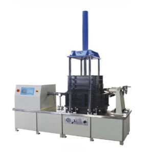
Structure and Components of the Geosynthetic Direct Shear and Pullout Friction Testing System
The Geosynthetic Direct Shear and Pullout Friction Testing System consists of several key components that work together to accurately evaluate the interface friction behavior between geosynthetic materials and surrounding soils or other engineering materials.
1. Loading System
The loading system is responsible for applying the required forces during testing and typically includes:
Vertical loading device for applying normal pressure
Horizontal loading device for applying shear force or pullout force
Depending on the testing requirements and equipment configuration, common loading methods include:
Mechanical lever and dead-weight loading
Hydraulic loading systems
Servo motor-controlled loading systems
Electro-mechanical loading systems
The loading system ensures precise control of loading rate, load magnitude, and test stability, allowing simulation of actual field stress conditions.
2. Shear Box and Pullout Box
The shear box and pullout box are the core testing chambers of the system.
Direct Shear Box
The direct shear test is conducted using a shear box, which generally consists of upper and lower sections that can move relative to each other. During testing:
The geosynthetic specimen is placed at the interface between the testing materials.
A normal load is applied vertically.
The lower or upper section is displaced horizontally to create shear movement.
This arrangement enables the measurement of interface shear resistance under controlled loading conditions.
Pullout Box
The pullout test is performed using a pullout box designed to simulate the anchorage conditions of geosynthetics embedded in soil.
Key features include:
Large-capacity soil containment chamber
Specimen clamping and anchoring system
Adjustable normal loading mechanism
The box can be filled with soil, aggregates, or other engineering materials to replicate real-world geotechnical conditions. During testing, the geosynthetic specimen is pulled from the surrounding material while resistance forces are measured.
3. Sensor System
The sensor system provides accurate measurement of forces and displacements throughout the testing process.
Load Sensors
Load sensors are used to measure:
Horizontal shear force
Pullout force
Vertical normal load
Interface resistance forces
High-precision load cells ensure reliable force measurement and data accuracy.
Displacement Sensors
Displacement sensors monitor:
Shear displacement
Pullout displacement
Deformation during loading
Movement rate and travel distance
These measurements help establish the load-displacement and stress-displacement relationships required for engineering analysis.
4. Measurement and Control System
The measurement and control system serves as the operational center of the testing equipment and typically consists of:
Industrial computer or control workstation
Data acquisition system
Motion controller
Control software
Signal conditioning modules
Its primary functions include:
Controlling the loading process
Monitoring test status in real time
Collecting sensor data continuously
Displaying force, displacement, and stress parameters
Automatically generating test curves
Analyzing and processing experimental results
Storing, exporting, and printing test reports
Modern systems often feature user-friendly software interfaces that provide automated testing procedures, real-time graphical displays, and comprehensive data management capabilities.
Summary
The Geosynthetic Direct Shear and Pullout Friction Testing System integrates a loading system, shear box and pullout box, sensor system, and computerized measurement and control system into a comprehensive testing platform. Through the coordinated operation of these components, the system can accurately evaluate the interface friction, shear strength, and pullout resistance of geosynthetic materials, providing reliable data for geotechnical engineering research, quality control, and structural design applications.
Industries and Applications of the Geosynthetic Direct Shear and Pullout Friction Testing System
The Geosynthetic Direct Shear and Pullout Friction Testing System is widely used in the fields of transportation engineering, hydraulic engineering, civil engineering, environmental engineering, material research, quality inspection, and academic research. It is primarily employed to evaluate the interface friction behavior between geosynthetic materials—such as geotextiles, geogrids, and geomembranes—and soil or other construction materials.
By providing accurate measurements of interface shear strength, pullout resistance, and friction characteristics, the system supports engineering design, material development, quality control, and scientific research.
1. Transportation Engineering
The testing system is extensively used in transportation infrastructure projects, including:
Highways and expressways
Railways and high-speed rail systems
Airport runways and embankments
Retaining walls and reinforced earth structures
Bridge approaches and slope stabilization projects
Engineers use the test results to evaluate soil–geosynthetic interaction and optimize the design of reinforced soil structures, ensuring long-term stability and safety.
2. Hydraulic and Water Conservancy Engineering
In hydraulic engineering applications, the system is used for projects such as:
Earth dams and embankments
Flood-control levees
Irrigation and drainage canals
Reservoir lining systems
Riverbank protection works
Coastal and marine engineering structures
The test data help assess the interface behavior between geosynthetics and soil under various loading conditions, supporting the design of effective seepage control and reinforcement systems.
3. Civil Engineering and Environmental Engineering
The system plays an important role in both civil and environmental engineering projects, including:
Landfill liner and cover systems
Waste containment facilities
Slope reinforcement and stabilization
Foundation reinforcement projects
Retaining structures
Ground improvement applications
Interface sliding and stability analysis
Accurate evaluation of interface friction properties is essential for predicting the long-term performance and safety of these structures.
4. Material Development and Quality Inspection
Geosynthetic manufacturers and testing organizations use the equipment for:
New product research and development
Product performance verification
Factory quality control testing
Product certification programs
Compliance testing according to international and national standards
Third-party inspection and verification services
The system provides reliable experimental data for assessing the engineering performance of geosynthetic materials before they are introduced into the market.
5. Universities and Research Institutions
Academic institutions and research laboratories utilize the testing system for:
Soil–structure interaction studies
Interface mechanics research
Reinforced soil behavior analysis
Geotechnical engineering experiments
Graduate and undergraduate laboratory teaching
Development of new testing methodologies
The equipment serves as an important platform for both scientific research and engineering education.
Conclusion
The Geosynthetic Direct Shear and Pullout Friction Testing System is a versatile and essential testing instrument for a wide range of industries. From transportation and hydraulic engineering to environmental protection, material development, and academic research, the system provides critical data for evaluating the interaction between geosynthetics and surrounding materials. Its results support safer designs, improved material performance, and more reliable geotechnical engineering solutions.
Technical Features of the Geosynthetic Direct Shear and Pullout Friction Testing System
1. Modular and User-Friendly Structural Design
The system features a compact and well-engineered modular structure. When switching between direct shear testing and pullout friction testing modes, the corresponding modules can be connected, removed, and installed quickly and conveniently. This flexible design significantly improves operational efficiency, reduces setup time, and simplifies routine maintenance, making the equipment suitable for both laboratory research and industrial testing applications.
2. Intuitive Control and Data Processing Software
The testing system is equipped with a powerful yet user-friendly control and data analysis software package. The software provides:
A clear and intuitive graphical user interface (GUI)
Logical function layout and menu structure
Simple and straightforward operating procedures
Real-time parameter monitoring and display
Even users with limited testing experience can become proficient after basic training, ensuring efficient operation and minimizing the likelihood of human error during testing.
3. Remote Operation and Technical Support Capability
The system supports remote access, operation, and monitoring through network connectivity. Users can perform test supervision and equipment management from different locations, improving convenience and operational flexibility.
In addition, manufacturers typically provide:
Remote technical assistance
Online troubleshooting services
Continuous technical support
Free software upgrades and updates
These services help ensure that the equipment remains up-to-date and operates at optimal performance throughout its service life.
4. High-Precision Automatic Control and Data Acquisition
The entire testing process is controlled automatically by a microcomputer-based control system, ensuring precise load application and accurate test execution.
Key features include:
High-precision automatic loading control
Real-time data acquisition
Dynamic display of test curves and parameters
Continuous monitoring of force and displacement data
Automatic data storage and management
The system can generate real-time graphical representations of test results, allowing operators to observe testing progress and specimen behavior throughout the experiment.
5. Powerful Data Analysis and Reporting Functions
The integrated software provides comprehensive data processing and reporting capabilities, including:
Automatic calculation of test parameters
Generation of load-displacement and stress-displacement curves
Statistical analysis of test results
Automatic creation of detailed test reports
Export of data in multiple file formats
Report printing and archiving functions
These features improve data accuracy, standardize result documentation, and significantly enhance laboratory productivity.
Conclusion
The Geosynthetic Direct Shear and Pullout Friction Testing System combines modular construction, easy operation, remote accessibility, high-precision automated control, and advanced data analysis capabilities into a single comprehensive testing platform. These technical advantages not only improve testing efficiency and reliability but also provide accurate and repeatable data for geotechnical engineering research, quality control, material development, and engineering design applications.
Test Methods of the Geosynthetic Direct Shear and Pullout Friction Testing System
The Geosynthetic Direct Shear and Pullout Friction Testing System mainly employs two testing methods: Direct Shear Friction Testing and Pullout Friction Testing.
1. Direct Shear Friction Test Method
Specimen Preparation
Place the specimen flat on the rigid horizontal base located in the lower section of the shear box, with the front end secured at the front of the shear area.
Bond the specimen to the base using a suitable adhesive. (If a P80 aluminum oxide standard friction base is used, bonding may not be necessary.)
After installation, ensure that the specimen is:
Flat and smooth
Free from folds and wrinkles
Firmly attached to the base
No relative slippage between the specimen and the base is permitted during the test.
Installation of the Upper Shear Box
Install the upper shear box.
Fill the upper shear box with pre-weighed standard sand (provided by the user).
The soil filling thickness should be 50 mm.
Ensure the sand layer is evenly distributed.
After compaction, the dry density should reach:
1.750 kg/m³
Application of Normal Load
Install the horizontal loading device.
Apply a normal pressure of 50 kPa using the standard loading weights.
The system is typically supplied with:
One reference weight corresponding to 50 kPa
Three additional standard weights
Each additional weight increases the normal stress by 50 kPa.
Typical normal stress levels:
50 kPa
100 kPa
150 kPa
200 kPa
Shearing Procedure
Apply a horizontal load to generate relative movement between the upper and lower shear boxes.
The shear displacement rate shall be:
1.0 ± 0.2 mm/min
Continuously or intermittently measure:
Shear force (T)
Relative displacement (ΔL)
Data recording intervals are typically:
Every 12 seconds
Higher recording frequency may be adopted during the initial loading stage if necessary.
Continue the test until the relative displacement reaches:
16.5% of the shear plane length
Terminate the test upon reaching the specified displacement.
Operating Procedure
Turn on the main power supply.
Start the system.
Enter the startup password:
000000
Select New Test from the operating menu.
Enter the required test speed and confirm.
The display will show:
Shear Force
Shear Stress
Peak Value
Displacement
Press the Start button to begin the test.
The system automatically performs tests under progressively increasing normal pressures:
50 kPa
100 kPa
150 kPa
200 kPa
Displacement measurement starts automatically.
When the displacement reaches 16.5% of the total contact length, the test stops automatically.
The test results are displayed on the screen.
If the data are valid, press Confirm.
Open the Result Query menu to review the test data.
Press Print to generate the test report.
The printer automatically outputs the complete test report.
2. Pullout Friction Test Method
Specimen Preparation
Cut the specimen according to the specified dimensions.
The specimen width should be slightly smaller than the width of the pullout box.
The specimen length should be sufficient to prevent tensile rupture during testing.
The exact dimensions may be determined according to the test requirements.
Number of Specimens
A minimum of three specimens shall be tested for each test condition.
End Reinforcement
Reinforce the exposed end of the specimen extending from the pullout box.
Excessive deformation of the external specimen portion should be avoided during testing.
Soil Placement in Lower Box
Carefully compact soil into the lower half of the pullout box according to the specified density and moisture condition.
Fill the soil up to the slot opening level.
Level the soil surface.
Specimen Placement
Place the specimen flat on the prepared soil surface.
Extend the pullout end through the slot opening.
Ensure symmetrical alignment on both sides.
Cover the specimen with a thin layer of soil to maintain its position.
Filling of Upper Soil Layer
Fill and compact soil into the upper half of the test box.
Maintain the specified density and state required by the test design.
Clamping the Specimen
Place the free end of the specimen into the pullout clamp.
Align the specimen carefully.
Tighten the clamp uniformly to avoid stress concentration.
Application of Normal Pressure
Install the loading cover plate.
Apply the required normal pressure.
Allow consolidation time according to the relevant testing standards and specifications.
Pullout Testing Procedure
Adjust the horizontal loading device.
Set the required testing parameters.
Use the up/down adjustment keys to position the pullout clamp.
The point at which the pullout clamp first begins to carry load is defined as the start of pullout.
Press the Start button to begin the test.
Continuously record:
Pullout displacement
Horizontal pullout force
The pullout rate may follow applicable geotechnical testing standards.
For sandy soils, a typical pullout rate is:
0.5 mm/min
Test Completion
Continue loading until the pullout force reaches its peak value.
Continue pulling after the peak force is reached.
When the pullout force stabilizes and remains relatively constant, stop the test.
Repeat Testing
Replace the specimen with a new one.
Apply a different normal pressure level.
Repeat the above procedure until all required test conditions have been completed.
Test Results
The direct shear test and pullout test provide critical parameters for evaluating soil–geosynthetic interaction, including:
Interface shear strength
Interface friction coefficient
Peak shear stress
Residual shear stress
Pullout resistance
Bond strength
Reinforcement effectiveness
Load-displacement characteristics
These results provide a reliable basis for the design, analysis, and quality assessment of geosynthetic applications in transportation, hydraulic, environmental, and geotechnical engineering projects.
Importance of the Geosynthetic Direct Shear and Pullout Friction Testing System
The primary significance of the Geosynthetic Direct Shear and Pullout Friction Testing System lies in its ability to quantitatively determine the interface friction characteristics between soil and geosynthetic materials. The test results provide critical design parameters for evaluating the sliding resistance and stability of geotechnical structures such as slopes, retaining walls, landfills, reinforced soil structures, embankments, and foundation reinforcement systems.
1. Ensuring Engineering Safety
Geosynthetic materials are widely used to reinforce soil masses and serve as separation, filtration, drainage, and impermeable barrier layers in geotechnical engineering projects. The interface shear strength between the geosynthetic material and surrounding soil directly affects the stability and safety of the entire structure.
By applying controlled normal stresses and horizontal shear or pullout loads, the testing system accurately simulates real-world soil–geosynthetic interaction conditions. This enables engineers to determine critical parameters such as interface friction coefficient, shear strength, and pullout resistance, helping to prevent structural instability or catastrophic failures caused by underestimating interface friction performance.
2. Optimizing Material Selection and Construction Practices
The testing system allows comprehensive evaluation of the factors that influence interface friction behavior, including:
Soil type and gradation
Geosynthetic material type
Surface texture and geometry
Moisture content
Compaction degree
Applied normal stress levels
By analyzing these variables, engineers can make informed decisions regarding material selection, design optimization, and construction quality control, ultimately improving project performance and cost-effectiveness.
3. Supporting the Development of Advanced Geosynthetic Materials
As modern geotechnical engineering increasingly adopts innovative materials such as:
Geogrids
Fiber-reinforced geosynthetics
Composite geomembranes
Geocomposites
High-performance reinforcement systems
the need for reliable evaluation of soil–material interaction becomes increasingly important.
The Geosynthetic Direct Shear and Pullout Friction Testing System serves as an essential research and development tool, enabling manufacturers, laboratories, and research institutions to verify the collaborative behavior between soil and geosynthetic materials and accelerate the development of next-generation engineering solutions.
4. Promoting Sustainable and Reliable Infrastructure Development
Accurate interface friction data contribute directly to the design of safer, more efficient, and more sustainable infrastructure projects. By ensuring that reinforcement and containment systems perform as intended throughout their service life, the testing system supports the implementation of environmentally responsible and resource-efficient engineering practices.
In simple terms, without accurate interface friction parameters between soil and geosynthetic materials, it is impossible to design reinforced soil structures, impermeable systems, retaining structures, or other soil–structure interaction projects in a safe and economical manner.The Geosynthetic Direct Shear and Pullout Friction Testing System acts as a critical measurement bridge connecting material performance with structural safety, providing engineers with the reliable data required for sound design, risk reduction, and long-term project success.If you would like to learn more about the Geosynthetic Direct Shear and Pullout Friction Testing System, we warmly welcome you to leave a message on our website or contact us directly. Our team will be pleased to provide detailed product information, technical specifications, application guidance, and professional consultation tailored to your testing requirements.
Previous: What are the applications and features of Porton Thermal Manikin Equipment?
N e x t : What are the principles and functions of Male Side Impact Dummy (RE Type)?
