


How to use the Air Flow Velocity Distribution Test System?
2026/05/19
Share:
Technical Features of the Air Flow Velocity Distribution Test System
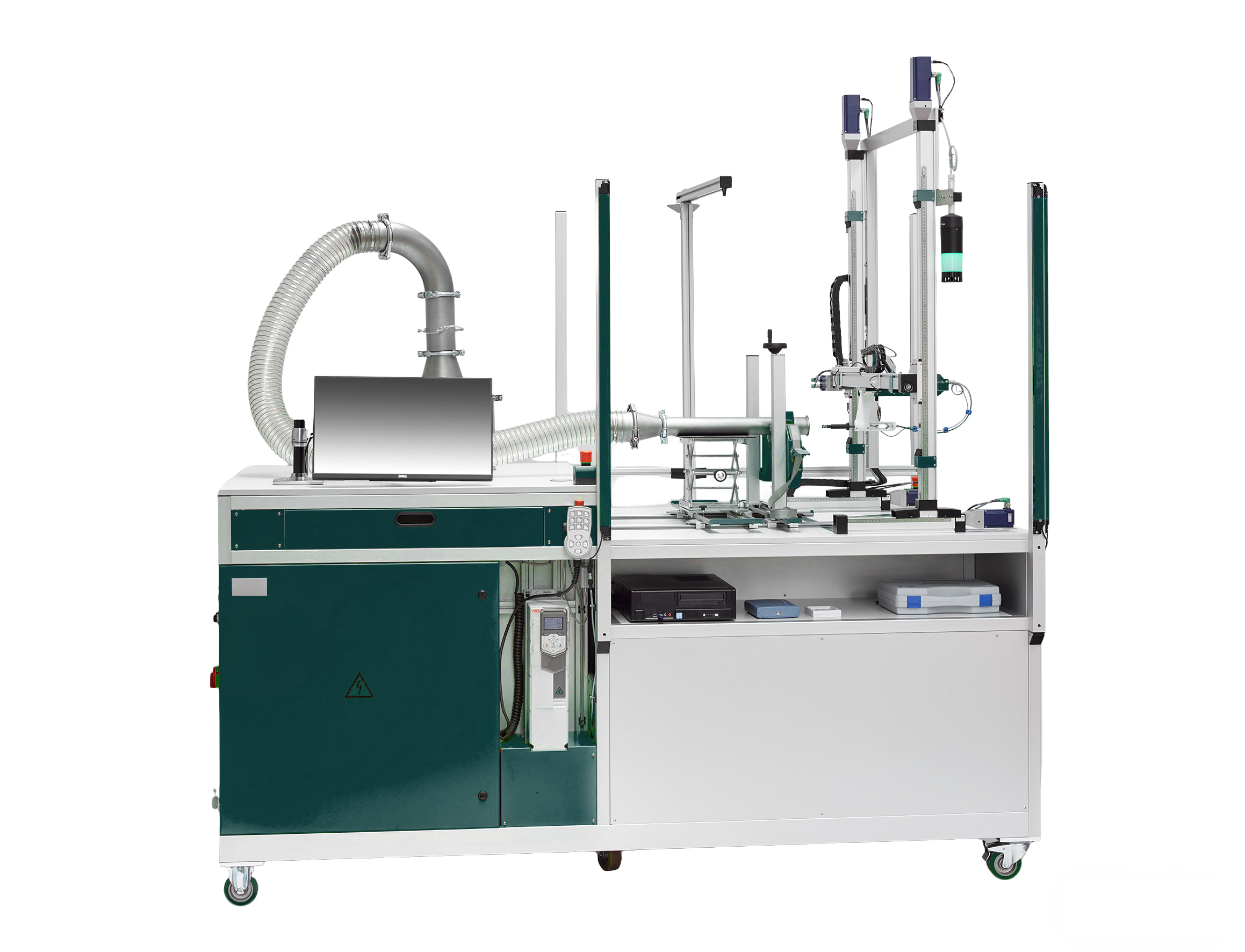
The Air Flow Velocity Distribution Test System is a specialized device designed to accurately measure, analyze, and visualize the velocity vectors and intensity distribution of airflow within a specific space or across a sectional area. The system is widely used in automotive engineering, aerospace, architectural wind tunnels, mine ventilation, and HVAC (Heating, Ventilation, and Air Conditioning) applications, aiming to solve performance evaluation challenges caused by uneven airflow distribution.
The following are the core technical features of the system:
1. High-Density Multi-Point Synchronous Acquisition Capability
Traditional single-point measurements cannot accurately reflect the overall characteristics of a flow field. Modern testing systems therefore adopt array-based sensor layouts.
Multi-sensor integration:
The system typically arranges a large number of airflow velocity sensors—such as hot-wire anemometers, Pitot tube arrays, or ultrasonic anemometers—across the test section to form a high-density measurement grid.
Synchronous data acquisition:
Through a high-speed Data Acquisition System (DAQ), all measurement points can be synchronously sampled at the millisecond level, ensuring accurate capture of transient airflow fluctuations and avoiding flow-field reconstruction errors caused by time desynchronization.
Full-coverage monitoring:
For complex sections such as engine intake manifolds, radiator front ends, or mine tunnels, the system can capture the complete distribution characteristics ranging from the central high-speed region to the low-speed laminar boundary layer near the walls.
2. Advanced Flow Rectification and Stability Control
To ensure the accuracy of the measurement baseline, the front end of the system is usually equipped with precision airflow conditioning devices, especially effective in open-circuit wind tunnels or dedicated testing benches.
Multi-stage flow rectification structure:
Honeycomb flow straighteners are used to eliminate large-scale vortices, while multi-layer damping screens suppress small-scale turbulence, controlling airflow angular deviation within ≤0.5° and reducing turbulence intensity to ≤1% (premium designs can achieve ≤0.3%).
Optimized contraction section:
A high-precision curved contraction section (typically with a contraction ratio of 8:1 to 12:1) accelerates the airflow and further improves flow uniformity, providing stable incoming airflow conditions for testing.
3. Intelligent Data Processing and 3D Visualization
The system not only outputs raw data but also emphasizes deep data analysis and intuitive visualization.
Real-time image analysis:
Combined with image processing technology, the system can generate airflow velocity profiles, contour maps, and 3D perspective views, visually presenting airflow distribution patterns.
Dynamic simulation and calculation:
Some high-end systems integrate ventilation simulation algorithms capable of performing online calculations based on real-time sensing data, enabling dynamic prediction of airflow distribution and abnormality diagnosis.
Big data correlation analysis:
The system can synchronously record airflow distribution together with pressure, temperature, engine operating conditions, and other multidimensional parameters. This allows analysis of the time-density relationship between throttle position and intake airflow distribution, thereby optimizing power performance.
4. High Adaptability and Environmental Compatibility
To meet different application requirements, the system is designed with high flexibility and environmental adaptability.
Compatibility with open and closed systems:
The system is suitable for both open-circuit wind tunnels (convenient for smoke flow visualization and internal combustion engine testing with direct atmospheric discharge) and closed-loop wind tunnels used in high-precision laboratory environments.
Anti-interference design:
The air inlet is equipped with guide hoods or grilles to prevent interference from external crosswinds. In harsh environments such as mines, the sensors feature dust-proof, moisture-proof, and vibration-resistant designs capable of handling non-uniform airflow patterns characterized by “high velocity in the center and low velocity around the edges.”
Wide-range adjustment capability:
Variable-frequency motor-driven fans enable stepless airflow velocity regulation (typically ranging from 3–60 m/s, with maximum speeds up to 80 m/s), meeting testing requirements under different Mach number conditions.
5. Automated Control and Safety Interlock Functions
Modern testing systems are increasingly moving toward fully automated operation to reduce human error and improve safety.
Intelligent closed-loop control:
Based on PLCs or industrial computer control systems, the system automatically adjusts fan speed and guide vane angles according to preset targets, maintaining stable airflow velocity within the test section.
Remote monitoring and decision-making:
Integrated with IoT technology, the system supports remote monitoring, control, and autonomous decision-making modules, enabling precise matching between ventilation parameter monitoring and control facilities, thereby improving testing efficiency.
Safety protection mechanisms:
The system is equipped with emergency stop buttons, safety guardrails, and overload protection devices to ensure the safety of personnel and equipment, especially in large-scale wind tunnels or high-pressure testing environments.
Air Flow Velocity Distribution Test System Operating Procedure
The Air Flow Velocity Distribution Test System is widely used in aircraft intake and exhaust system wind tunnel testing, vehicle cooling system performance evaluation, and HVAC (Heating, Ventilation, and Air Conditioning) airflow balancing applications. Its core objective is to obtain airflow velocity vectors, pressure distribution, and flow characteristics at various points within the flow field, thereby evaluating aerodynamic performance, flow stability, and system compatibility.
The following is a standardized operating procedure compiled based on general engineering standards and high-precision wind tunnel/testing bench specifications.
I. Pre-Test Preparation Stage
This stage aims to ensure that the testing environment, equipment, and test object are in a controlled and compliant condition.
1. Define Test Objectives and Operating Conditions
Determine the test object:
Identify whether the tested component is an air intake duct, exhaust nozzle, radiator module, or air-conditioning outlet.
Define key performance indicators:
According to industry standards, determine the parameters to be measured, including total pressure recovery coefficient ((\sigma)), distortion index ((D_{c60})), flow coefficient, thrust coefficient, or noise spectrum.
Set operating conditions:
Define boundary conditions such as Mach number (Ma), angle of attack, sideslip angle, engine speed, or fan operating level.
2. Model Installation and Boundary Simulation Configuration
Model fixation:
Securely install the test specimen (such as a scaled model or full-size component) in the wind tunnel test section or testing bench, ensuring that its axis is aligned with the incoming airflow direction.
Connection of power simulation devices:
If using an ejector simulator:
Connect the high-pressure air source and inspect the ejector throat condition to ensure the intake suction effect can simulate more than 90% of the actual airflow rate.
If using a Turbine Power Simulator (TPS):
Start auxiliary systems, preheat, and inspect bearing temperature and vibration values to ensure the simulator can accurately reproduce both intake airflow and exhaust jet pressure ratio.
Back pressure control system setup:
For exhaust system testing, adjust the back pressure control valve so that the exhaust back pressure remains within the preset range (typically 0.5–2.0 times atmospheric pressure), simulating different flight altitudes or ground operating conditions.
3. Sensor Calibration and Arrangement
Pressure probe array:
Install total/static pressure probe arrays at the intake outlet or compressor inlet section to measure pressure recovery and flow field distortion.
Deployment of velocity measurement equipment:
Hot-Wire Anemometer (HWA):
Used for high-frequency pulsation measurements and requires prior cold-wire compensation calibration.
Pitot tube:
Used for average airflow velocity measurement, ensuring the probe faces directly into the airflow direction.
PIV (Particle Image Velocimetry) system:
For non-contact full-field velocity vector measurement, arrange laser sheet light sources and high-speed cameras while uniformly dispersing tracer particles within the flow field.
Data acquisition synchronization:
Connect multi-point pressure scanning valves, flowmeters, temperature sensors, and acoustic microphone arrays, ensuring a sampling rate of (\ge 100 \text{ kHz}) for synchronized signal acquisition.
4. Safety and Environmental Inspection
Protective facility confirmation:
Check whether debris shields and anti-surge bypass valves are functioning properly.
Environmental parameter monitoring:
Record laboratory ambient temperature, humidity, and atmospheric pressure. If necessary, activate rainfall/spray or low-temperature icing simulation systems to verify performance under specific environmental conditions.
II. System Startup and Pre-Debugging
1. No-Load Trial Operation
Start the main wind tunnel fan or driving unit and gradually increase airflow speed under no-load or low-load conditions.
Check the incoming airflow turbulence intensity downstream of the honeycomb flow straightener and damping screens, ensuring it remains within 1%–3%.
Verify the response accuracy of the Mass Flow Controller (MFC), with errors controlled within ±1%.
2. Baseline Data Acquisition
Acquire background flow field data without the test specimen installed or with a standard calibration component installed for subsequent data correction and subtraction.
Check whether all sensor channels are functioning properly and eliminate open circuits, short circuits, or noise interference.
III. Formal Testing Procedure
1. Steady-State Operating Condition Testing
Gradual loading:
According to the preset operating condition table, gradually adjust airflow speed, angle of attack, or simulated engine power.
Stabilization waiting period:
Maintain each operating point for sufficient time until pressure, temperature, and flow readings fluctuate within the allowable error range (typically stable for 30 seconds to several minutes).
Data acquisition:
Record static pressure distribution, total pressure recovery coefficient, and distortion index.
If using PIV, trigger laser pulses and camera imaging to obtain instantaneous velocity vector fields.
Record exhaust noise spectra and sound pressure levels (dB), and perform beamforming acoustic source localization.
2. Dynamic/Transient Condition Testing (If Applicable)
Step response testing:
Rapidly change throttle lever angle or fan speed to simulate takeoff, acceleration, or emergency braking conditions.
High-frequency sampling:
Enable high-speed data acquisition mode to capture transient characteristics such as flow separation, shock wave movement, and surge/stall boundaries.
Visualization observation:
Use smoke generators or high-speed cameras to record separated vortex structures and jet diffusion patterns.
3. Airflow Balancing Adjustment (For HVAC Systems)
Reference outlet method:
Select the outlet in the most unfavorable loop as the reference and adjust airflow at other outlets according to the designed proportional values.
Proportional airflow distribution method:
Adjust branch dampers so that airflow in each branch is distributed according to the design ratio, ultimately ensuring that each supply outlet meets the specified airflow requirement.
Repeated measurements:
Re-measure after each adjustment until airflow deviation at all outlets satisfies specification requirements (typically ≤10%).
IV. Data Processing and Analysis
1. Raw Data Cleaning
Remove outliers and perform zero-drift correction.
Apply standardized corrections for ambient temperature and atmospheric pressure, converting measurements to standard-condition parameters.
2. Calculation of Key Performance Indicators
Intake systems:
Calculate the total pressure recovery coefficient (\sigma = P_{out}/P_{in}) and distortion index (D_{c60}) to evaluate compressor inlet flow field uniformity.
Exhaust systems:
Calculate thrust coefficient (C_F) and exhaust resistance coefficient to analyze interference losses between the exhaust jet and external airflow.
Cooling/HVAC systems:
Plot radiator efficiency curves and compare airflow distribution uniformity and heat exchange efficiency with and without airflow-guiding wind tunnels.
3. Flow Field Visualization Analysis
Combine CFD simulation data with wind tunnel test results to analyze flow separation locations, shock wave structures, and vortex evolution mechanisms.
Identify potential aerodynamic instability regions (such as surge boundaries) and propose optimization recommendations.
V. Test Completion and Shutdown
1. System Shutdown
Gradually reduce fan speed or simulated engine power to avoid thermal shock or sudden pressure changes.
Shut down high-pressure air sources, laser systems, and precision instruments, and release residual pressure in pipelines.
2. Equipment Maintenance
Clean residual tracer particles inside the wind tunnel test section.
Inspect sensor probes for damage or contamination, especially hot-wire anemometer probes, which require careful storage.
Back up all raw data and processed reports for archival and traceability purposes.
3. Preliminary Conclusion Reporting
Compare measured data with design expectations to determine whether the tested system meets aerodynamic performance, noise, and emission requirements. If significant deviations are identified (such as excessive distortion index or excessive thrust loss), immediate retesting or model redesign should be arranged.
Precautions
Safety:
High-speed wind tunnel testing involves high-pressure gases and rotating machinery. Operators must wear protective equipment and strictly follow safety operating procedures.
Accuracy control:
Ensure that calibration certificates for all measuring instruments remain valid and perform regular on-site verification.
Environmental consistency:
Maintain stable ambient temperature and humidity as much as possible to minimize the influence of environmental factors on air density and fluid viscosity.
Importance of the Air Flow Velocity Distribution Test System
The importance of the Air Flow Velocity Distribution Test System lies in its ability to accurately quantify the spatial and temporal characteristics of airflow, providing a scientific basis for improving safety, efficiency, and performance across multiple critical fields. Its core significance is reflected in the following aspects:
1. Ensuring Safety
Laboratory Safety:
Through fume hood face velocity distribution testing, the system can identify “safety dead zones,” ensuring that hazardous gases are effectively captured and preventing personnel exposure to dangerous environments.
Fire Protection and Smoke Exhaust:
In building fire scenarios, airflow organization testing verifies whether smoke exhaust systems can rapidly remove smoke, preventing smoke backflow or accumulation and ensuring the safety of evacuation routes.
Industrial Safety:
In environments such as chemical plants and tunnels, real-time airflow monitoring helps prevent the accumulation of combustible gases or excessive concentrations of hazardous gases.
2. Improving Energy Efficiency and Environmental Protection
Ventilation System Optimization:
By identifying areas with uneven airflow velocity, the system helps avoid over-ventilation or insufficient local ventilation, significantly reducing energy consumption (for example, tunnel ventilation systems can achieve energy savings exceeding 50%).
Supporting Green Building Design:
The system provides reliable data support for HVAC (Heating, Ventilation, and Air Conditioning) systems and cleanrooms, enabling demand-based air supply and reducing carbon emissions.
3. Ensuring Product Quality and Process Stability
Textile Industry:
The airflow velocity distribution of weft insertion nozzles in air-jet looms directly affects weft yarn insertion stability and fabric quality. The testing system can quantitatively evaluate critical parameters such as high-speed airflow concentration and symmetry.
Electronics and Pharmaceutical Cleanrooms:
The system ensures the uniformity of unidirectional laminar airflow, preventing particle deposition and meeting stringent standards such as GMP requirements.
4. Supporting R&D and Regulatory Compliance
Product Development:
The system provides a comparative testing platform for new nozzles, ventilation equipment, fans, and related products, accelerating product optimization and design improvement.
Regulatory Compliance:
Test results can verify compliance with domestic and international standards such as GB, ISO, and ASHRAE, providing legally recognized validation data.
5. Enabling Intelligent Operation and Maintenance
Dynamic Monitoring:
Combined with multi-point sensors and remote data acquisition technology, the system supports adaptive adjustment of ventilation systems, such as automatically regulating tunnel fan speed according to traffic flow conditions.
Predictive Maintenance:
By continuously analyzing airflow fluctuation patterns, the system can identify potential equipment aging or blockage risks in advance.
In summary, the Air Flow Velocity Distribution Test System is not only a cornerstone for safety assurance and regulatory compliance, but also a key technological tool for achieving energy savings, quality improvement, operational efficiency, and intelligent system upgrades.We sincerely welcome you to leave a message or contact us directly so that we can provide you with more detailed product information.
Previous: What is the liquid batch dosing system?
N e x t : the last page
