


What is the air filter in a gas turbine?
2026/05/29
Share:
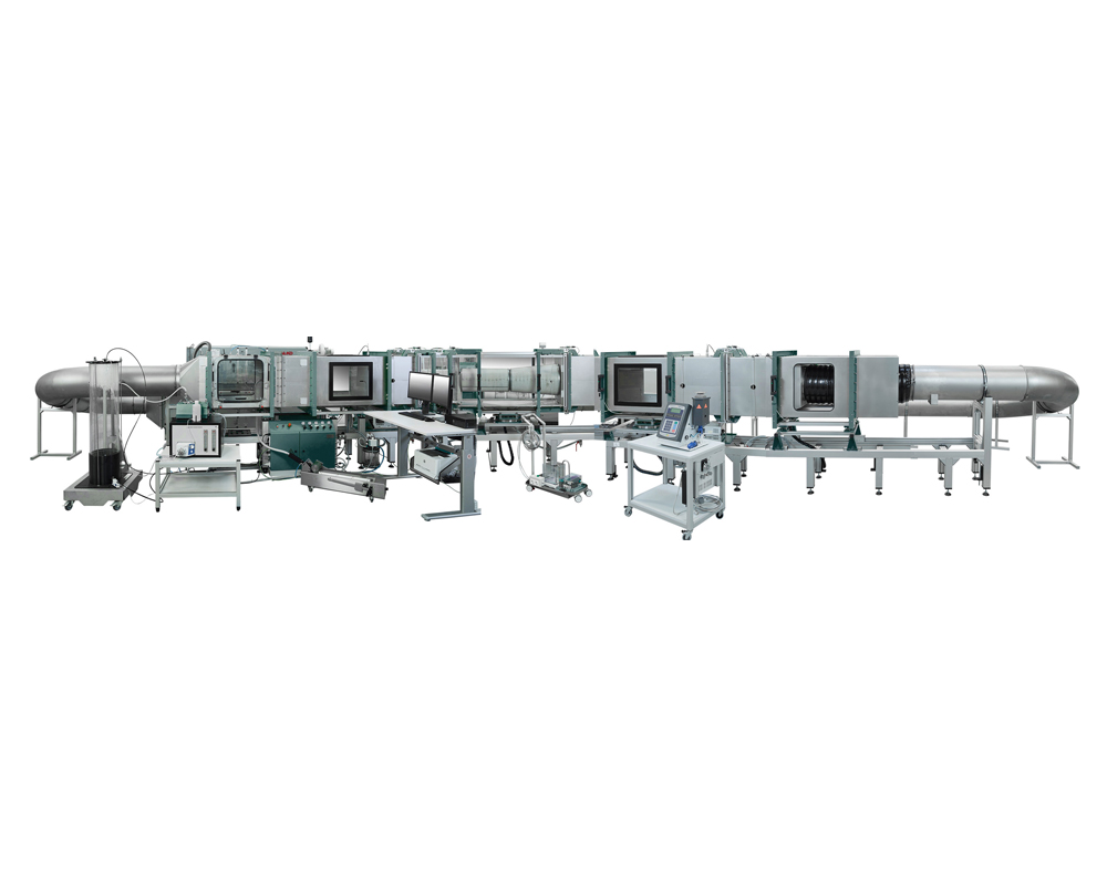
Functions and Applications of the Gas Turbine Filter Test System
The function of the Gas Turbine Filter Test System is to simulate real intake air conditions in order to evaluate the filtration efficiency, pressure drop characteristics, dust holding capacity, and durability of gas turbine air filters. Its purpose is to ensure that filters maintain clean intake air for gas turbines under harsh operating conditions, thereby preventing compressor corrosion, fouling, and efficiency degradation.
Function:
Under controlled conditions—such as specified dust concentration, humidity, and airflow rate—the system tests the filter’s:
initial filtration efficiency,
dust holding capacity,
differential pressure growth curve,
and pulse cleaning performance (if applicable).
Testing is typically conducted in accordance with standards such as ISO, ASHRAE, or IEC.
Application:
The system is used to verify whether filters meet the intake air cleanliness requirements specified by gas turbine manufacturers or power plants, such as:
filtration efficiency ≥99.95% for particles in the 1–5 μm range,
and pressure drop limits (e.g., final pressure drop ≤2.5 in. H₂O).
It helps prevent compressor fouling and erosion, improve unit availability, thermal efficiency, and service life, and is also widely used for:
R&D comparison,
quality acceptance inspection,
and operation & maintenance decision support.
Applicable Industries of the Gas Turbine Filter Test System
The Gas Turbine Filter Test System is mainly applicable to the following industries:
Power generation industry
Including gas turbine power plants for both base-load and peak-load operation, where the system is used to verify the efficiency and durability of intake filtration systems under conditions such as dust and salt fog exposure.
Oil & gas exploration and refining
Used in offshore platforms, onshore oilfields, refineries, and related facilities to test the filter’s capability to capture salt mist, hydrocarbons, and corrosive aerosols.
Industrial drive systems and manufacturing industry
Applied to industrial gas turbines used for driving compressors, pumps, and other equipment, ensuring clean intake air to prevent compressor wear and corrosion.
Marine and offshore engineering
Used for gas turbines in ships and offshore installations, with emphasis on validating water resistance and salt protection performance under high-humidity and high-salinity environments.
Aerospace and defense industry
Certain ground-based test platforms are used for simulation and evaluation of intake filtration systems for aviation gas turbines and turboshaft engines. Although not intended for onboard testing, many related standards are compatible.
Environmental protection and research institutions
Universities, national laboratories, and third-party testing organizations use the system for developing advanced filtration materials and verifying compliance with standards such as ISO.
Technical Features of the Gas Turbine Filter Test System
The core technical features of the Gas Turbine Filter Test System focus on efficiently, stably, and repeatedly evaluating filter pressure drop characteristics, dust holding capacity, and filtration efficiency under real operating conditions, especially for submicron particles.
High-Precision Dynamic Loading Simulation
The system continuously injects standardized test dust at actual environmental concentrations (e.g., 1–5 g/m³) to simulate extreme sandstorm or industrial contamination conditions, ensuring that test results accurately reflect the harshest field operating environments.
Real-Time Pressure Drop and Efficiency Monitoring
The system integrates:
high-response differential pressure sensors (accuracy ±0.1% FS),
and particle counters capable of detecting particle sizes from 0.01–10 μm, typically using OPC or laser Doppler technology.
It simultaneously records:
initial filter pressure drop,
pressure rise rate during dust loading,
and graded filtration efficiency.
Typical requirements include filtration efficiency ≥99.95% for particles in the 0.5–1 μm range.
Steady-State and Pulse-Cleaning Dual-Mode Operation
The system supports:
constant airflow continuous loading (e.g., 100–10.000 CFM),
as well as pulse-jet cleaning simulation through alternating high- and low-pressure zones.
This enables evaluation of performance degradation of filter media such as pleated synthetic fiber or fiberglass filter elements during cleaning cycles.
Full-Scale or Reduced-Scale Wind Tunnel Structure
Most professional systems adopt test sections close to the dimensions of actual turbine intake ducts in order to minimize edge effects.
The system is also equipped with temperature and humidity control functions (typically 20–40°C and 30–70% RH) to simulate environmental influences on filter performance.
Automation and Standards Compliance
The system complies with standards such as ISO, EN, or ASTM, and utilizes SCADA systems for automatic data acquisition.
It can generate key performance outputs including:
pressure drop vs. dust holding curves,
initial and average filtration efficiency,
and final pressure drop limits (typically ≤2.5 in. W.G.).
The system also supports filter service life prediction and performance analysis.
This type of system is not intended for testing filter mechanical strength or fuel filtration performance. It is specifically designed for evaluating particulate interception performance in gas turbine air intake systems, with the primary goal of preventing compressor blade erosion and fouling while ensuring turbine availability and emissions compliance.
Operating Procedure of the Gas Turbine Filter Test System
Operating a Gas Turbine Filter Test System typically involves a series of procedures to ensure testing accuracy and operational safety. The following is a standard workflow covering preparation, testing, analysis, and maintenance.
1. Preparation Stage
a. Equipment Inspection
Check whether the filter test system and all components are in good condition.
Confirm that all connections and pipelines are correctly installed and free from leakage.
b. Preparation of Tools and Materials
Prepare required testing instruments such as pressure gauges, flow meters, and thermometers.
Prepare filter samples as well as any required testing chemicals or cleaning agents.
c. Cleaning the Work Area
Ensure that the working area is clean and organized to prevent dust or contaminants from affecting the test samples.
2. System Calibration
a. Calibration of Pressure and Flow Instruments
Use standard calibration equipment to calibrate pressure gauges and flow meters to ensure accurate readings.
b. Temperature Calibration
Inspect and calibrate temperature sensors to ensure temperature measurement accuracy.
3. Filter Installation
a. Filter Mounting
Correctly install and secure the filter to be tested into the test system.
b. System Leak Inspection
Check all connection points to ensure the system is properly sealed and leak-free.
4. Parameter Configuration
a. Setting Test Parameters
Configure airflow, pressure, temperature, and other parameters according to the test requirements.
Set the test duration and cycle count.
5. Test Execution
a. Start the Test
Start the test system according to the predefined testing parameters.
Monitor system operation continuously to ensure all parameters remain within the specified range.
b. Data Recording
Record key parameters such as pressure, airflow, and temperature in real time.
Record filter performance indicators including filtration efficiency and resistance variation.
6. Test Completion and Result Analysis
a. End the Test
Stop the test once the preset testing time or cycle count has been reached.
Shut down the test system and disconnect the power supply.
b. Result Analysis
Analyze the recorded data to evaluate filter performance.
Examine indicators such as differential pressure before and after the filter and airflow variation to determine filtration effectiveness.
7. Cleaning and Maintenance
a. Filter Cleaning
Clean or replace the filter as required to ensure the accuracy of future tests.
Clean all internal components of the testing system, especially the areas surrounding the filter.
b. System Maintenance
Inspect and record system maintenance status.
Perform regular maintenance and servicing according to maintenance schedules.
8. Report Preparation and Documentation
a. Test Report Preparation
Prepare a detailed test report based on the test results.
The report should include:
test parameters,
recorded data,
result analysis,
and recommendations.
b. Report Archiving
Archive all test reports for future reference and auditing purposes.
By following the above procedures, the Gas Turbine Filter Test System can be operated effectively while ensuring accurate and reliable testing results. During operation, all safety regulations and operating procedures should be strictly followed to ensure the safety of personnel and equipment.
Importance of the Gas Turbine Filter Test System
The Gas Turbine Filter Test System is critically important because it ensures that intake air filters can effectively block contaminants such as dust, salt mist, and sand particles under harsh operating conditions, thereby protecting the efficiency, service life, and operational safety of gas turbines.
Protection of Critical Components
Unfiltered particles can erode compressor blades, block cooling passages, and cause compressor surge, corrosion, or unplanned shutdowns. The repair costs associated with such failures can reach millions of dollars.
Maintaining Thermal Efficiency and Power Output
Contamination buildup increases airflow resistance and reduces compression efficiency, directly decreasing gas turbine output power (often by more than 5%) while simultaneously increasing fuel consumption.
Performance Verification Under Real Operating Conditions
Laboratory testing can simulate environments with:
high humidity,
high salinity,
and heavy dust concentration,
allowing evaluation of:
filtration efficiency (e.g., ≥99.5% at MPPS),
dust holding capacity,
pressure drop characteristics,
and water resistance performance.
This helps prevent situations where filters appear compliant in specifications but fail under actual field conditions.
Support for Filter Selection and Maintenance Decisions
By obtaining full lifecycle performance data through dynamic testing, the system can support:
filter type selection (such as pulse self-cleaning filters vs. panel filters),
replacement interval optimization,
and predictive maintenance planning,
thereby reducing the LCOE (Levelized Cost of Electricity).
Ensuring System Sealing and Reliability
Testing can identify design defects such as:
bypass leakage,
structural deformation,
and sealing failures,
preventing contaminants from bypassing the filter media and directly entering the gas turbine. Such bypass leakage is one of the most common failure modes in field operation.
Overall, without standardized and repeatable filtration system testing, it is impossible to provide reliable intake air protection for modern high-precision, high-speed gas turbines. The test system serves as the only trustworthy bridge connecting filter R&D, quality acceptance, and real-world operational performance.We sincerely welcome you to leave a message or contact us directly so that we can provide more detailed product information and technical support.
Previous: What is the Automotive Cargo Cover Screw Inspection Line?
N e x t : the last page
